III. INSTALLATION (continued)
III.f - CORD & PLUG:
All Traulsen Blast Chill models (except model RBC100 which is supplied with a cord set but no plug) are supplied with a cord & plug attached (for models RBC200 and RBC200RT, the cord and plug supplied is for the
III.g - ELECTRICAL REQUIREMENTS:
Model RBC50 is normally provided with two (2) grounding type cords with plugs (NEMA
| Fig. 4 |
115/60/1 | 115/60/1 |
Outlet #1 | Outlet #2 |
Model RBC100 is normally provided with a grounding type cord without a plug. A dedicated 220/60/1 volt, 4 wire, 20 amp grounded circuit with receptacle should be provided by a certified electrician to assure that the computerized control is not adversely affected by the operation of other equipment.
Models RBC200/RBC200RT are normally provided with one (RBC400/RBC400RT are provided with two) grounded cordset (NEMA
III.h - PROPER CLEARANCES:
Model RBC50: Make certain that there are no obstructions in front of the louver panels on the left and right front sides of the unit. This will allow for sufficient air flow to the re- frigeration system and maintenance access.
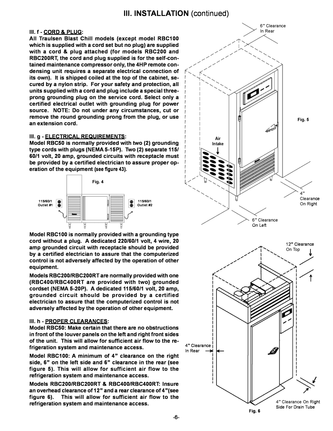
Model RBC100: A minimum of 4” clearance on the right side, 6” on the left side and 6” clearance in the rear (see figure 5). This will allow for sufficient air flow to the refrigeration system and maintenance access.
Models RBC200/RBC200RT & RBC400/RBC400RT: Insure an overhead clearance of 12” and a rear clearance of 4”(see figure 6). This will allow for sufficient air flow to the refrigeration system and maintenance access.
6” Clearance
In Rear
Fig. 5
Air
Intake
↓
4” Clearance On Right
6” Clearance
On Left
12” Clearance
On Top | ↓ |
| |
| ↑ |
4” Clearance |
|
In Rear ↑ | ↑ |
↑
↑
4” Clearance On Right
Side For Drain Tube
Fig. 6