6 – Standard Operation
6-1 Control Panel Features
2 |
| 3 |
| 4 |
| 5 |
| 6 | |||||
|
|
|
|
|
|
|
|
|
|
|
|
|
|
1
7 | 8 | 9 | 10 | 11 | 12 |
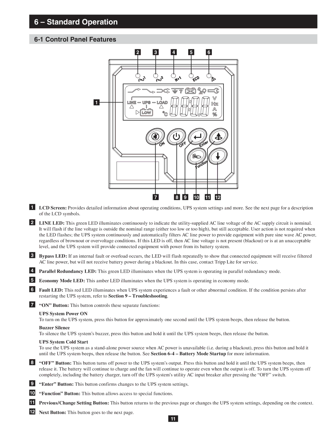
1LCD Screen: Provides detailed information about operating conditions, UPS system settings and more. See the next page for a description of the LCD symbols.
2LINE LED: This green LED illuminates continuously to indicate the
3Bypass LED: If an internal fault or overload occurs, the LED will flash repeatedly to show that connected equipment will receive filtered AC line power, but will not receive battery power during a blackout. In this case, contact Tripp Lite for service.
4Parallel Redundancy LED: This green LED illuminates when the UPS system is operating in parallel redundancy mode.
5Economy Mode LED: This amber LED illuminates when the UPS system is operating in economy mode.
6Fault LED: This red LED illuminates when UPS system experiences a fault or other abnormal condition. If the condition persists after restarting the UPS system, refer to Section 9 – Troubleshooting.
7“ON” Button: This button controls these separate functions:
UPS System Power ON
To turn on the UPS system, press this button for approximately one second until the UPS system beeps, then release the button.
Buzzer Silence
To silence the UPS system’s buzzer, press this button and hold it until the UPS system beeps, then release the button.
UPS System Cold Start
To use the UPS system as a
8“OFF” Button: This button turns off power to the UPS system’s output. Press this button and hold it until the UPS system beeps, then release it. The battery will continue to charge and the fan will continue to operate even when the output is off. To turn the UPS system off completely, including the battery charger, turn off the UPS system’s utility AC input breaker after pressing the “OFF” switch.
9“Enter” Button: This button confirms changes to the UPS system settings.
10“Function” Button: This button allows access to special functions.
11Previous/Change Setting Button: This button returns to the previous page or changes the UPS system settings, depending on the context.
12Next Button: This button goes to the next page.
11
