3 – Rear Panel Features |
|
|
| |
Note: Refer to Section |
|
|
| |
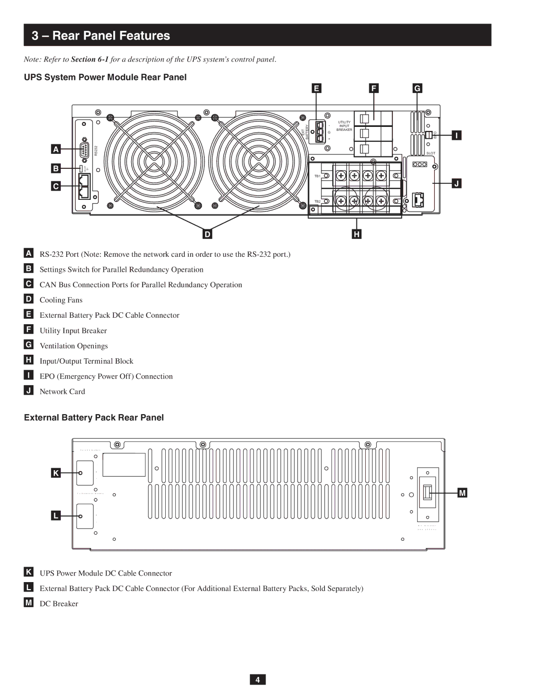
UPS System Power Module Rear Panel |
|
|
| |
|
| E | F | G |
| EXT. BATTERY | - | UTILITY |
|
| INPUT | EPO | ||
| G | BREAKER | ||
|
|
| ||
|
|
|
| |
|
| + |
|
|
A | RS232 |
|
| SLOT |
B | ON OFF S1 |
|
|
|
|
| TB1 |
|
|
C |
|
|
|
|
|
| TB2 |
|
|
| D |
| H |
|
A
BSettings Switch for Parallel Redundancy Operation
CCAN Bus Connection Ports for Parallel Redundancy Operation
DCooling Fans
EExternal Battery Pack DC Cable Connector
FUtility Input Breaker
GVentilation Openings
HInput/Output Terminal Block
IEPO (Emergency Power Off) Connection
JNetwork Card
External Battery Pack Rear Panel
T o U P S B a t t e r y
-
K G
+
T o E x t e n d e d B a t t e r y
-
L G
+
D C B r e a k e r
3 0 A 2 5 0 V d c
KUPS Power Module DC Cable Connector
LExternal Battery Pack DC Cable Connector (For Additional External Battery Packs, Sold Separately)
MDC Breaker
I
J
M
4