6 – Standard Operation continued
6-3 Normal Mode Startup
1.Confirm that the UPS system is properly grounded.
2.Make sure the utility AC supply circuit breaker and the UPS system’s input breaker are switched off.
3.Wire the utility AC supply circuit and output circuit to the UPS system’s terminal block and connect the external battery pack, following the instructions in Section 5 – Wiring.
4.Switch on the utility AC supply circuit breaker and the UPS system’s input breaker. The green line LED (![]() ) illuminates continuously to indicate the
) illuminates continuously to indicate the
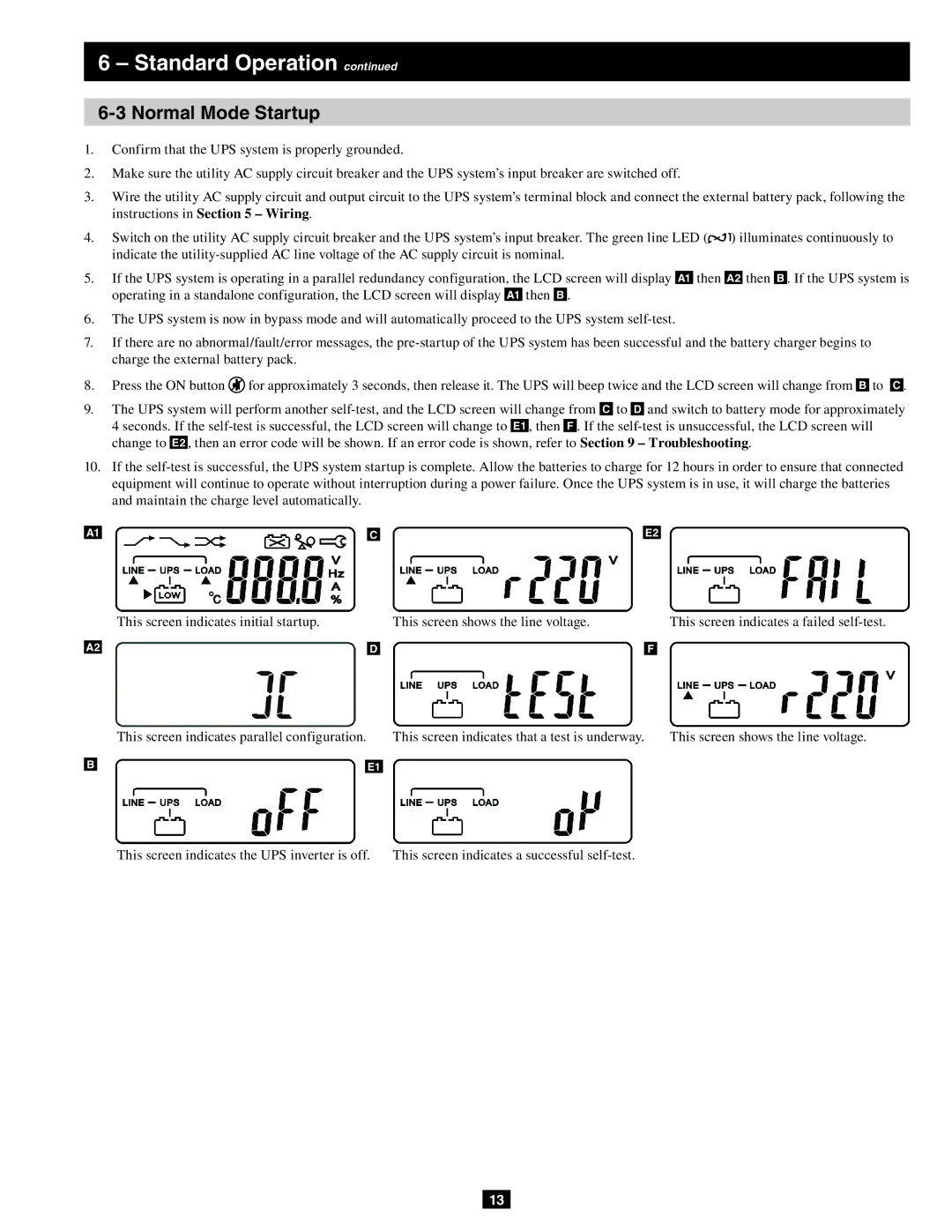
5.If the UPS system is operating in a parallel redundancy configuration, the LCD screen will display A1 then A2 then B . If the UPS system is operating in a standalone configuration, the LCD screen will display A1 then B .
6.The UPS system is now in bypass mode and will automatically proceed to the UPS system
7.If there are no abnormal/fault/error messages, the
8. Press the ON button | for approximately 3 seconds, then release it. The UPS will beep twice and the LCD screen will change from B to C . |
9.The UPS system will perform another
10.If the
A1 |
| C |
| E2 |
|
|
|
|
|
| This screen indicates initial startup. | This screen shows the line voltage. | ||
|
|
|
|
|
A2 |
| D |
| F |
| This screen indicates parallel configuration. |
| This screen indicates that a test is underway. |
|
| ||
B |
|
|
|
E1 |
| ||
|
|
|
|
This screen indicates a failed
This screen shows the line voltage.
This screen indicates the UPS inverter is off. | This screen indicates a successful |
13