4 – Mounting continued
4-2 Placement
In order to minimize the possibility of damage to the UPS system and maximize its operational lifespan, follow the location warnings listed in Section 2 – Important Safety Instructions. Remember to keep at least 30 cm clearance from the rear panel of the UPS system to the wall and do not block any of the UPS system’s front or rear ventilation openings.
Warning: The UPS system is very
4-3 Mounting (Rack)
•Use the included rackmount shelves and mounting hardware to mount the UPS system in a
•The instructions in this manual are for common rack and rack enclosure types and may not be appropriate for all mounting applications. The user must determine the fitness of hardware and procedures before mounting. If hardware or procedures are not suitable for the application, contact the manufacturer of the rack or rack enclosure for a solution.
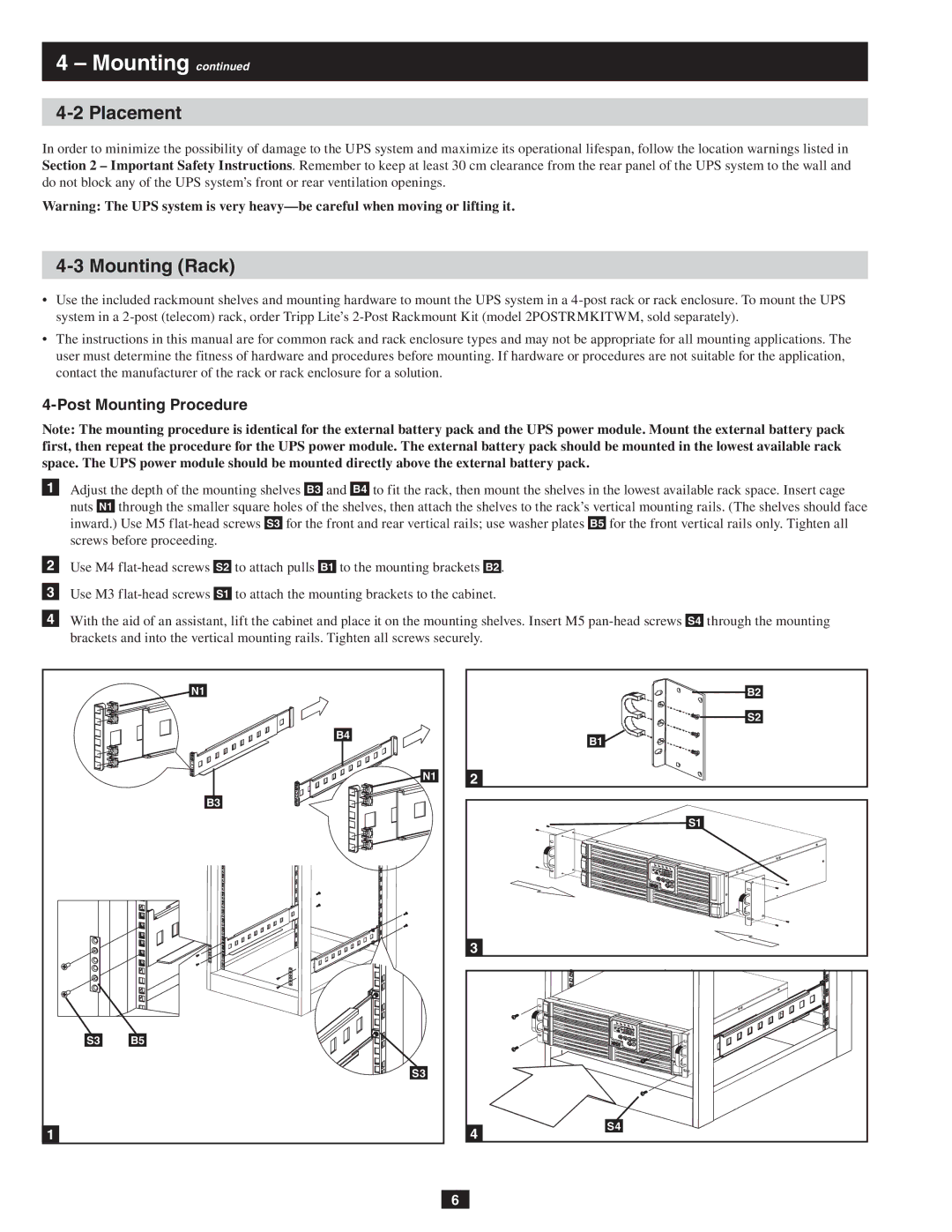
4-Post Mounting Procedure
Note: The mounting procedure is identical for the external battery pack and the UPS power module. Mount the external battery pack first, then repeat the procedure for the UPS power module. The external battery pack should be mounted in the lowest available rack space. The UPS power module should be mounted directly above the external battery pack.
1Adjust the depth of the mounting shelves B3 and B4 to fit the rack, then mount the shelves in the lowest available rack space. Insert cage nuts N1 through the smaller square holes of the shelves, then attach the shelves to the rack’s vertical mounting rails. (The shelves should face inward.) Use M5
2Use M4
3Use M3
4With the aid of an assistant, lift the cabinet and place it on the mounting shelves. Insert M5
| N1 |
| B4 |
| N1 |
| B3 |
S3 | B5 |
| S3 |
1 |
|
B2 |
S2 |
B1 |
2 |
S1 |
3 |
4 | S4 |
|
6