7 – Parallel Redundancy Operation (Optional)
DANGER! LETHAL HIGH VOLTAGE HAZARD!
All wiring should be performed by a qualified electrician, in accordance with the warnings in this manual and all applicable electrical and safety codes. Incorrect wiring may cause serious personal injury and property damage. Read, study and understand the warnings listed in Section 2 – Important Safety Instructions before proceeding.
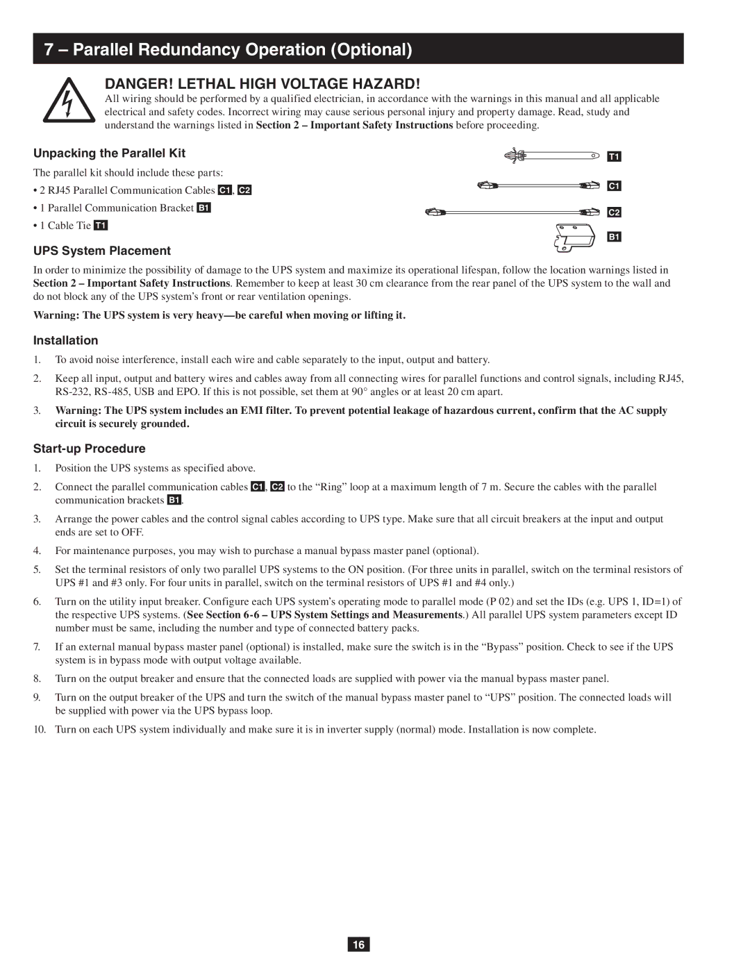
Unpacking the Parallel Kit |
|
T1 |
The parallel kit should include these parts:
• 2 | RJ45 Parallel Communication Cables |
| , |
|
| C1 | ||||
C1 | C2 |
| ||||||||
|
| |||||||||
• 1 | Parallel Communication Bracket |
|
|
|
|
|
|
| ||
B1 |
|
|
|
|
| |||||
|
|
|
| C2 | ||||||
• 1 | Cable Tie |
|
|
|
|
|
|
|
| |
|
|
|
|
|
|
| ||||
T1 |
|
|
|
|
| |||||
|
|
|
|
|
|
|
|
|
| B1 |
UPS System Placement
In order to minimize the possibility of damage to the UPS system and maximize its operational lifespan, follow the location warnings listed in Section 2 – Important Safety Instructions. Remember to keep at least 30 cm clearance from the rear panel of the UPS system to the wall and do not block any of the UPS system’s front or rear ventilation openings.
Warning: The UPS system is very
Installation
1.To avoid noise interference, install each wire and cable separately to the input, output and battery.
2.Keep all input, output and battery wires and cables away from all connecting wires for parallel functions and control signals, including RJ45,
3.Warning: The UPS system includes an EMI filter. To prevent potential leakage of hazardous current, confirm that the AC supply circuit is securely grounded.
Start-up Procedure
1.Position the UPS systems as specified above.
2.Connect the parallel communication cables C1 , C2 to the “Ring” loop at a maximum length of 7 m. Secure the cables with the parallel communication brackets B1 .
3.Arrange the power cables and the control signal cables according to UPS type. Make sure that all circuit breakers at the input and output ends are set to OFF.
4.For maintenance purposes, you may wish to purchase a manual bypass master panel (optional).
5.Set the terminal resistors of only two parallel UPS systems to the ON position. (For three units in parallel, switch on the terminal resistors of UPS #1 and #3 only. For four units in parallel, switch on the terminal resistors of UPS #1 and #4 only.)
6.Turn on the utility input breaker. Configure each UPS system’s operating mode to parallel mode (P 02) and set the IDs (e.g. UPS 1, ID=1) of the respective UPS systems. (See Section
7.If an external manual bypass master panel (optional) is installed, make sure the switch is in the “Bypass” position. Check to see if the UPS system is in bypass mode with output voltage available.
8.Turn on the output breaker and ensure that the connected loads are supplied with power via the manual bypass master panel.
9.Turn on the output breaker of the UPS and turn the switch of the manual bypass master panel to “UPS” position. The connected loads will be supplied with power via the UPS bypass loop.
10.Turn on each UPS system individually and make sure it is in inverter supply (normal) mode. Installation is now complete.
16