5 – Wiring
DANGER! LETHAL HIGH VOLTAGE HAZARD!
All wiring should be performed by a qualified electrician, in accordance with the warnings in this manual and all applicable electrical and safety codes. Incorrect wiring may cause serious personal injury and property damage. Read, study and understand the warnings listed in Section 2 – Important Safety Instructions before proceeding.
5-1 Wiring Preparation
•
•Mark all cables according to their correct purpose, polarity, phase and diameter.
•Review the diagram in Section
•Consult the table in Section
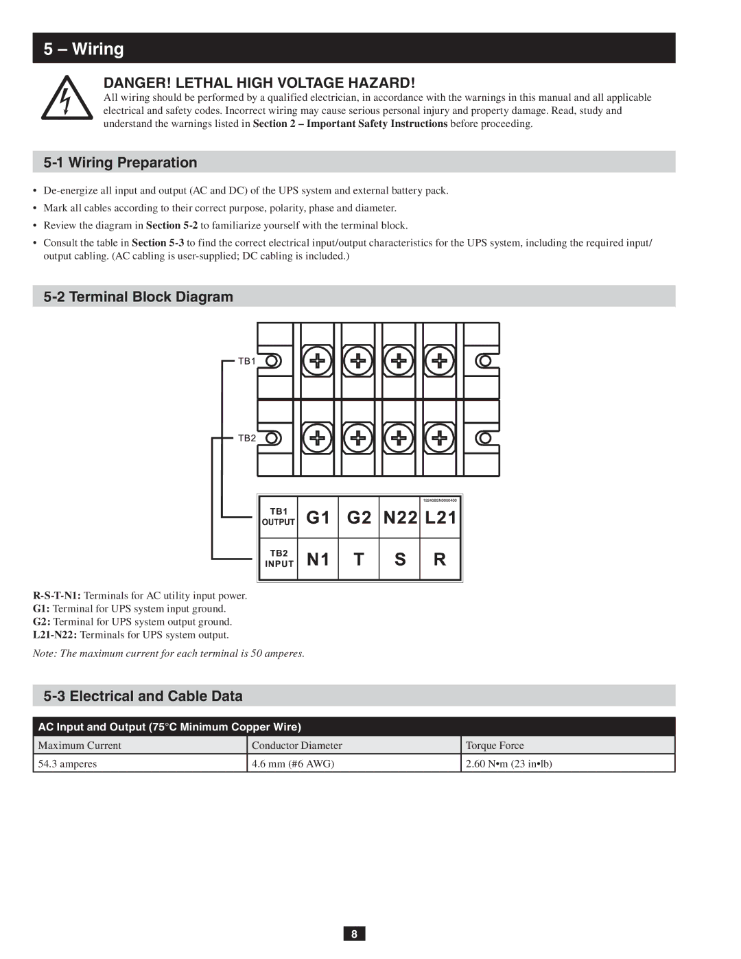
5-2 Terminal Block Diagram
G1: Terminal for UPS system input ground.
G2: Terminal for UPS system output ground.
Note: The maximum current for each terminal is 50 amperes.
5-3 Electrical and Cable Data
AC Input and Output (75°C Minimum Copper Wire)
Maximum Current | Conductor Diameter | Torque Force |
|
|
|
54.3 amperes | 4.6 mm (#6 AWG) | 2.60 N•m (23 in•lb) |
|
|
|
8