Contents
Tomcat K7M
Table of Contents
Before you begin… Check the box contents
Introduction
Form Factor
Power
Regulatory
OS Operating System Support
Installation
Board Installation
How to install our products right…. the first time
Board Image
S2498 Tomcat K7M Block Diagram
Block Diagram
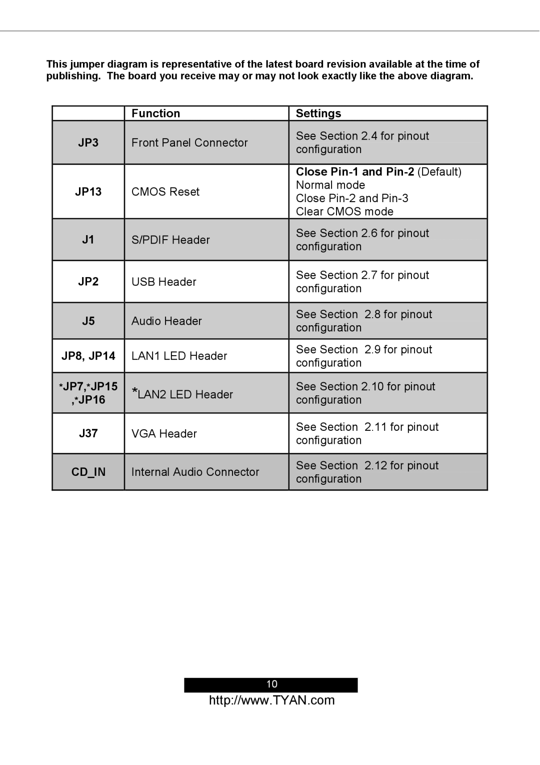
Board Parts, Jumpers and Connectors
JP7, *JP15
JP13
JP8, JP14
J37
PIN
Cmos
Cmos Reset JP13
Default
S/PDIF Header J1
USB Header JP2
Audio Header J5
LAN1 LED Header JP8, JP14
10 *LAN2 LED Header *JP7, *JP15, *JP16
Internal Audio Connector Cdin
VGA Header J37
Mounting the Motherboard
Installing the Memory
= 9 Chips Memory Installation Procedure
Installing the Processor and Heatsink
Finishing Installing the Heatsink
Attaching Drive Cables
Page
Page
Installing Add-In Cards
Installing the Power Supply
Connecting External Devices
Disconnect power supply from electrical outlet
Finishing Up
Setup Basics
Bios Setup
Starting Setup
Key Function
Setup Variations
Case of Problems
Getting Help
Main Bios Setup
Save & Exit Setup
Load Optimized Defaults
Supervisor / User Password
Exit Without Save
Date / Time Setup
Standard Cmos Features
Phoenix AwardBIOS Cmos Setup Utility Standard Cmos Features
IDE Master / Slave Setup
Video
Halt On
Advanced Bios Features
Typematic Rate Setting
Boot Up Floppy Seek
Boot Up NumLock Status
Typematic Delay Msec
Boot Other Device
Hard Disk Boot Priority
First / Second / Third Boot Device
Small Logo EPA Show
Memory Hole:
Advanced Chipsets Features
System Bios Cacheable
Video RAM Cacheable
Dram Clock
Current FSB Frequency
Current Dram Frequency
Dram Timing
AGP Mode
Dram Command Rate
Write Recovery Time
Active to CMD Trcd
AGP Fast Write
CPU Direct Access FB
TVConnector
AGP Master 1 WS Write
PCI1/PCI2 Master 0 WS Write
Phoenix AwardBIOS Cmos Setup Utility CPU & PCI Bus Control
PCI Delay Transaction
PCI1/PCI2 Post Write
Integrated Peripherals
Phoenix AwardBIOS Cmos Setup Utility Integrated Peripherals
VIA OnChip IDE Device Phoenix AwardBIOS Cmos Setup Utility
Init Display First
IDE HDD Block Mode
Sata Mode
IDE Prefetch Mode
VIA OnChip PCI Device Phoenix AwardBIOS Cmos Setup Utility
Onchip USB Controller
AC97 Audio
MC97 Modem
OnChip Ehci Controller
IR Transmission Delay
Super IO Device Phoenix AwardBIOS Cmos Setup Utility
Uart Mode Select
UR2 Duplex Mode
EPP Mode Select
Use IR Pins
Parallel Port Mode
ECP Mode Use DMA
Power Management Setup
Run Vgabois if S3 Resume
Modem Use IRQ
Soft-Off by Pwrbtn
Ac Loss Auto Restart
USB Resume from S3
PowerOn by PCI Card
RTC Alarm Resume
PCI Master
IRQ8, 9, 10, 11
Primary Intr
IRQ3,4, 5, 6, 7, 12, 13
PnP/PCI Configurations
Shutdown Temperature
Phoenix AwardBIOS Cmos Setup Utility PC Health Status
CPU Warning Temperature
PC Health Status
Spread Spectrum
Frequency/Voltage Control
Auto Detect PCI Clk
CPU Clock
Load Fail-Safe Defaults Y/N? N
Load Fail-Safe Defaults
Load Optimized Defaults
Load Optimized Defaults Y/N? N
Supervisor/User Password Setting
Enter Password
Password Disabled
Save to Cmos and Exit Y/N? Y
Exit Without Saving Phoenix AwardBIOS Cmos Setup Utility
Quit without saving Y/N? Y
Memory, Video, CPU Beep Codes
Diagnostics
Flash Utility
Appendix I Glossary
Page
Mirroring see RAID
Page
Page
Returning Merchandise for Service
Technical Support
Document # D1650-101