Installation |
|
|
|
|
|
|
|
|
|
|
|
|
|
| Tank Gauge Transmitter | |||||
|
|
|
|
|
|
|
|
|
|
|
|
|
|
|
|
|
|
|
|
|
|
|
|
|
|
|
|
|
|
|
|
|
|
|
|
|
|
|
|
|
|
|
|
|
|
|
|
|
|
|
|
|
|
|
|
|
|
|
|
|
|
|
|
|
|
|
|
|
|
|
|
|
|
|
|
|
|
|
|
|
|
|
|
|
|
|
|
|
|
|
|
|
|
|
|
|
|
|
|
|
|
|
|
|
|
|
|
|
|
|
|
|
|
|
|
|
|
|
|
|
|
|
|
|
|
|
|
|
|
|
|
|
|
|
|
|
|
|
|
|
|
|
|
|
|
|
|
|
|
|
|
|
|
|
|
|
|
|
|
|
|
|
|
|
|
|
|
|
|
|
|
|
|
|
|
|
|
|
|
|
|
|
|
|
|
|
|
|
|
|
|
|
|
|
|
|
|
|
|
|
|
|
|
|
|
|
|
|
|
|
|
|
|
|
|
|
|
|
|
|
|
|
|
|
|
|
|
|
|
|
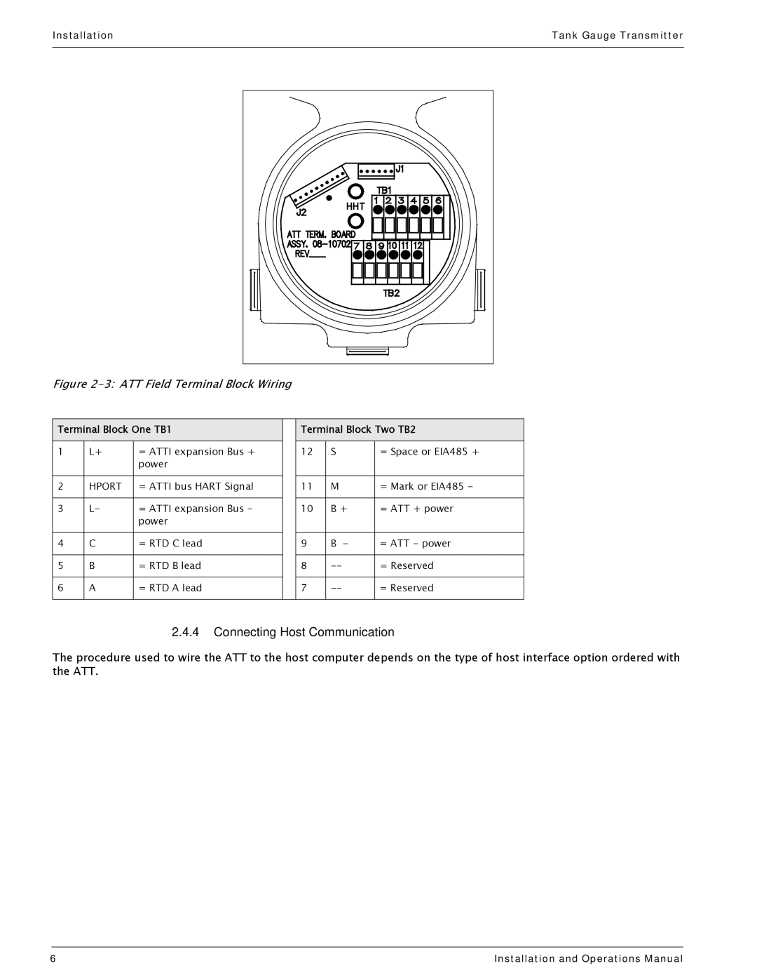
Figure 2-3: ATT Field Terminal Block Wiring
Terminal Block One TB1 |
| Terminal Block Two TB2 | ||||
1 | L+ | = ATTI expansion Bus + |
| 12 | S | = Space or EIA485 + |
|
| power |
|
|
|
|
|
|
|
|
|
|
|
2 | HPORT | = ATTI bus HART Signal |
| 11 | M | = Mark or EIA485 - |
|
|
|
|
|
|
|
3 | L- | = ATTI expansion Bus - |
| 10 | B + | = ATT + power |
|
| power |
|
|
|
|
|
|
|
|
|
|
|
4 | C | = RTD C lead |
| 9 | B - | = ATT - power |
|
|
|
|
|
|
|
5 | B | = RTD B lead |
| 8 | = Reserved | |
|
|
|
|
|
|
|
6 | A | = RTD A lead |
| 7 | = Reserved | |
|
|
|
|
|
|
|
2.4.4Connecting Host Communication
The procedure used to wire the ATT to the host computer depends on the type of host interface option ordered with the ATT.
6 | Installation and Operations Manual |