4000 | Modbus Implementation |
|
|
9.4Functions and Data Formats
The Modbus data in the ATT is arranged in integer registers, floating point registers, and status bits. The assignments for these registers are found at the end of this appendix.
Function codes 03, 04, 06, and 16 are used with integer registers.
Because of the multiple Modbus hosts available today, the ATT supports two
Function codes 01, 02, 05, and 15 are used with status bits.
A complete description of all the preceding commands, except floating point, can be found in the Modicon Modbus Protocol Reference Guide, document number
9.5Integer Registers
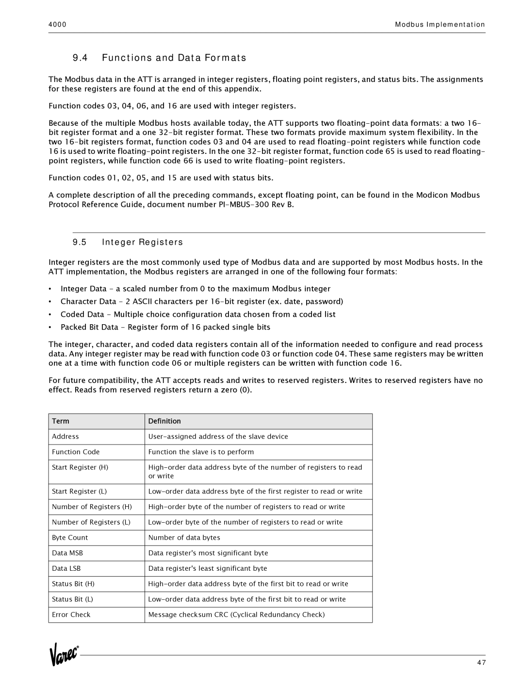
Integer registers are the most commonly used type of Modbus data and are supported by most Modbus hosts. In the ATT implementation, the Modbus registers are arranged in one of the following four formats:
•Integer Data - a scaled number from 0 to the maximum Modbus integer
•Character Data - 2 ASCII characters per
•Coded Data - Multiple choice configuration data chosen from a coded list
•Packed Bit Data - Register form of 16 packed single bits
The integer, character, and coded data registers contain all of the information needed to configure and read process data. Any integer register may be read with function code 03 or function code 04. These same registers may be written one at a time with function code 06 or multiple registers can be written with function code 16.
For future compatibility, the ATT accepts reads and writes to reserved registers. Writes to reserved registers have no effect. Reads from reserved registers return a zero (0).
Term | Definition |
Address | |
|
|
Function Code | Function the slave is to perform |
|
|
Start Register (H) | |
| or write |
|
|
Start Register (L) | |
|
|
Number of Registers (H) | |
|
|
Number of Registers (L) | |
|
|
Byte Count | Number of data bytes |
|
|
Data MSB | Data register's most significant byte |
|
|
Data LSB | Data register's least significant byte |
|
|
Status Bit (H) | |
|
|
Status Bit (L) | |
|
|
Error Check | Message checksum CRC (Cyclical Redundancy Check) |
|
|
47
