4000 | Modbus Implementation |
|
|
9.7Status Bits
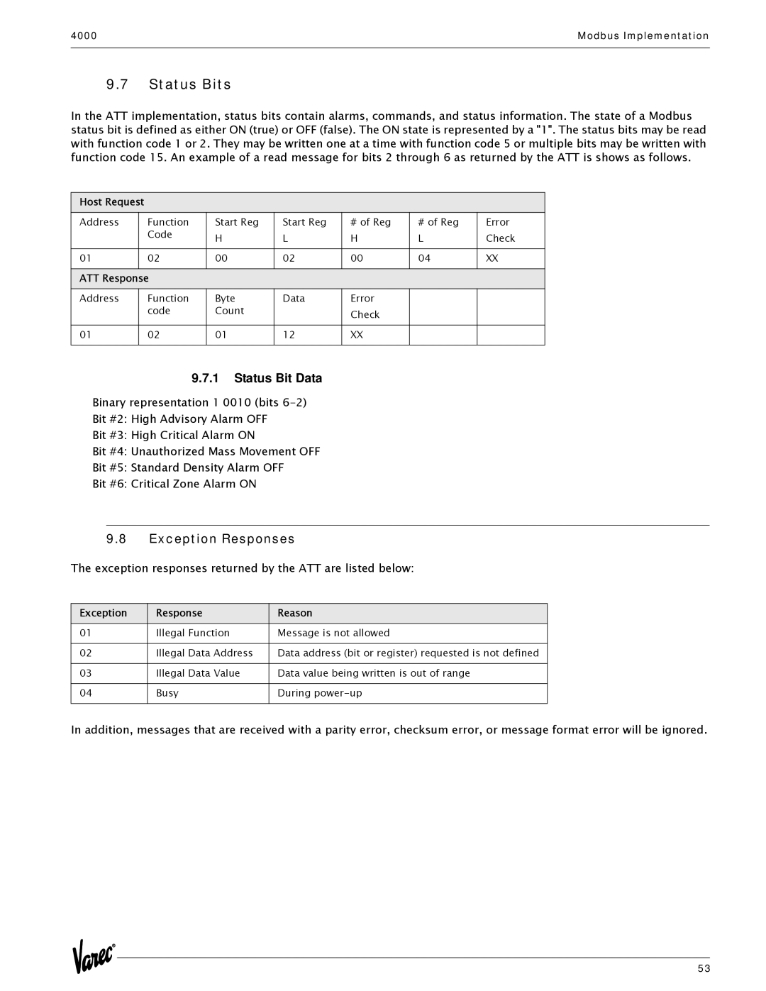
In the ATT implementation, status bits contain alarms, commands, and status information. The state of a Modbus status bit is defined as either ON (true) or OFF (false). The ON state is represented by a "1". The status bits may be read with function code 1 or 2. They may be written one at a time with function code 5 or multiple bits may be written with function code 15. An example of a read message for bits 2 through 6 as returned by the ATT is shows as follows.
Host Request
Address | Function | Start Reg | Start Reg | # of Reg | # of Reg | Error |
| Code | H | L | H | L | Check |
|
|
|
|
|
|
|
01 | 02 | 00 | 02 | 00 | 04 | XX |
|
|
|
|
|
|
|
ATT Response |
|
|
|
|
| |
Address | Function | Byte | Data | Error |
|
|
| code | Count |
| Check |
|
|
|
|
|
|
|
|
|
01 | 02 | 01 | 12 | XX |
|
|
|
|
|
|
|
|
|
9.7.1Status Bit Data
Binary representation 1 0010 (bits
Bit #2: High Advisory Alarm OFF
Bit #3: High Critical Alarm ON
Bit #4: Unauthorized Mass Movement OFF
Bit #5: Standard Density Alarm OFF
Bit #6: Critical Zone Alarm ON
9.8Exception Responses
The exception responses returned by the ATT are listed below:
Exception | Response | Reason |
01 | Illegal Function | Message is not allowed |
|
|
|
02 | Illegal Data Address | Data address (bit or register) requested is not defined |
|
|
|
03 | Illegal Data Value | Data value being written is out of range |
|
|
|
04 | Busy | During |
|
|
|
In addition, messages that are received with a parity error, checksum error, or message format error will be ignored.
53