Modbus Implementation | Tank Gauge Transmitter |
|
|
9.5.4Coded Data
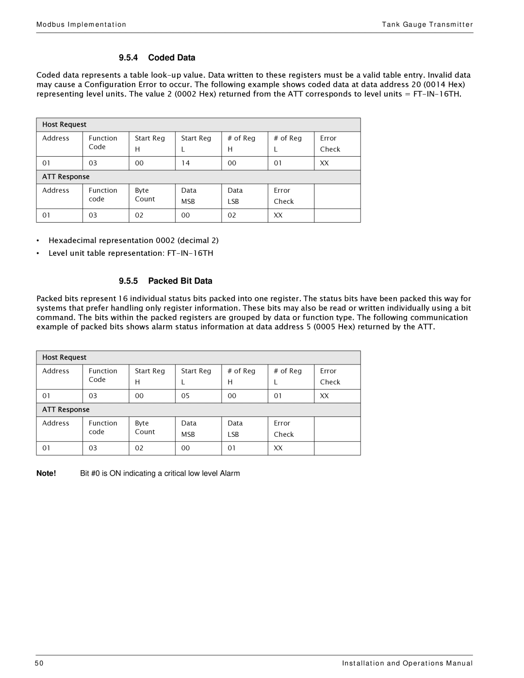
Coded data represents a table
Host Request
Address | Function | Start Reg | Start Reg | # of Reg | # of Reg | Error |
| Code | H | L | H | L | Check |
|
|
|
|
|
|
|
01 | 03 | 00 | 14 | 00 | 01 | XX |
|
|
|
|
|
|
|
ATT Response |
|
|
|
|
| |
Address | Function | Byte | Data | Data | Error |
|
| code | Count | MSB | LSB | Check |
|
|
|
|
|
|
|
|
01 | 03 | 02 | 00 | 02 | XX |
|
|
|
|
|
|
|
|
•Hexadecimal representation 0002 (decimal 2)
•Level unit table representation:
9.5.5Packed Bit Data
Packed bits represent 16 individual status bits packed into one register. The status bits have been packed this way for systems that prefer handling only register information. These bits may also be read or written individually using a bit command. The bits within the packed registers are grouped by data or function type. The following communication example of packed bits shows alarm status information at data address 5 (0005 Hex) returned by the ATT.
Host Request
Address | Function | Start Reg | Start Reg | # of Reg | # of Reg | Error |
| Code | H | L | H | L | Check |
|
|
|
|
|
|
|
01 | 03 | 00 | 05 | 00 | 01 | XX |
|
|
|
|
|
|
|
ATT Response |
|
|
|
|
| |
Address | Function | Byte | Data | Data | Error |
|
| code | Count | MSB | LSB | Check |
|
|
|
|
|
|
|
|
01 | 03 | 02 | 00 | 01 | XX |
|
|
|
|
|
|
|
|
Note! Bit #0 is ON indicating a critical low level Alarm
50 | Installation and Operations Manual |
