Modbus Implementation | Tank Gauge Transmitter |
|
|
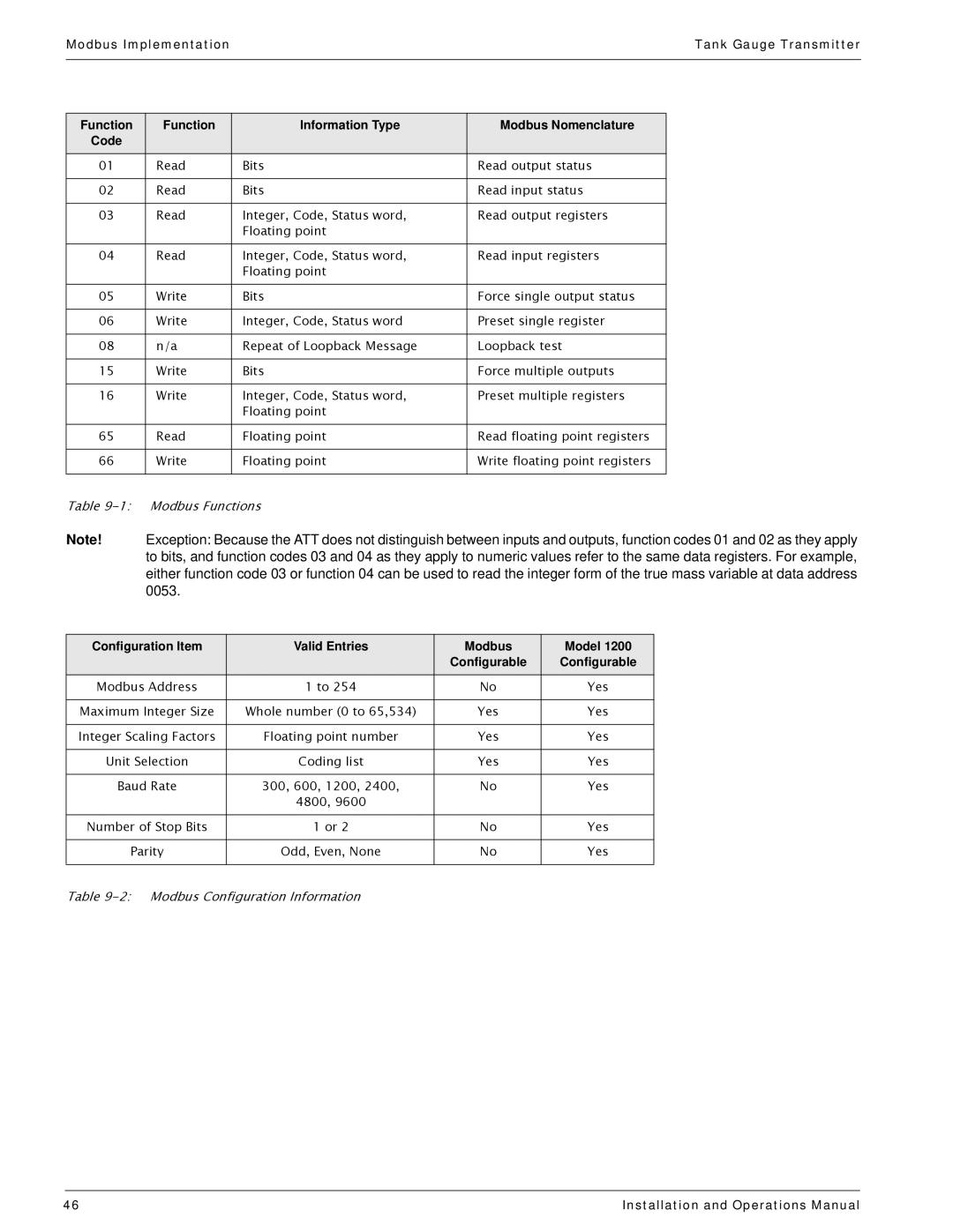
Function | Function | Information Type | Modbus Nomenclature |
Code |
|
|
|
01 | Read | Bits | Read output status |
|
|
|
|
02 | Read | Bits | Read input status |
|
|
|
|
03 | Read | Integer, Code, Status word, | Read output registers |
|
| Floating point |
|
04 | Read | Integer, Code, Status word, | Read input registers |
|
| Floating point |
|
05 | Write | Bits | Force single output status |
|
|
|
|
06 | Write | Integer, Code, Status word | Preset single register |
|
|
|
|
08 | n/a | Repeat of Loopback Message | Loopback test |
|
|
|
|
15 | Write | Bits | Force multiple outputs |
|
|
|
|
16 | Write | Integer, Code, Status word, | Preset multiple registers |
|
| Floating point |
|
65 | Read | Floating point | Read floating point registers |
|
|
|
|
66 | Write | Floating point | Write floating point registers |
|
|
|
|
Table
Note! Exception: Because the ATT does not distinguish between inputs and outputs, function codes 01 and 02 as they apply to bits, and function codes 03 and 04 as they apply to numeric values refer to the same data registers. For example, either function code 03 or function 04 can be used to read the integer form of the true mass variable at data address 0053.
Configuration Item | Valid Entries | Modbus | Model 1200 |
|
| Configurable | Configurable |
Modbus Address | 1 to 254 | No | Yes |
|
|
|
|
Maximum Integer Size | Whole number (0 to 65,534) | Yes | Yes |
|
|
|
|
Integer Scaling Factors | Floating point number | Yes | Yes |
|
|
|
|
Unit Selection | Coding list | Yes | Yes |
|
|
|
|
Baud Rate | 300, 600, 1200, 2400, | No | Yes |
| 4800, 9600 |
|
|
Number of Stop Bits | 1 or 2 | No | Yes |
|
|
|
|
Parity | Odd, Even, None | No | Yes |
|
|
|
|
Table
46 | Installation and Operations Manual |