Controls and Functions
1.CONNECTOR PANEL
Refer to Vision 50 Connector Panel, below.
2.POWER INPUT (100 to 240 VAC) Connect the Vision 50 to power here.
3.MAIN POWER SWITCH
Disconnects or applies power to the Vision 50.
4.
Refer to
5.CABLE ACCESS DOOR Open to access connectors.
6.DOOR RELEASE BUTTON
7.CABLE OPENING
Pass cables through this opening.
8.LAMP MODULE COVER
Remove this cover to access the lamp compartment.
9.FRONT/REAR ADJUSTERS
Use these to adjust the projector height or projection angle.
10.CEILING MOUNT HOLES
Use these to attach the ceiling bracket to the projector.
To access the connector panel, press the door release button so it pops out. Turn the knob clockwise or
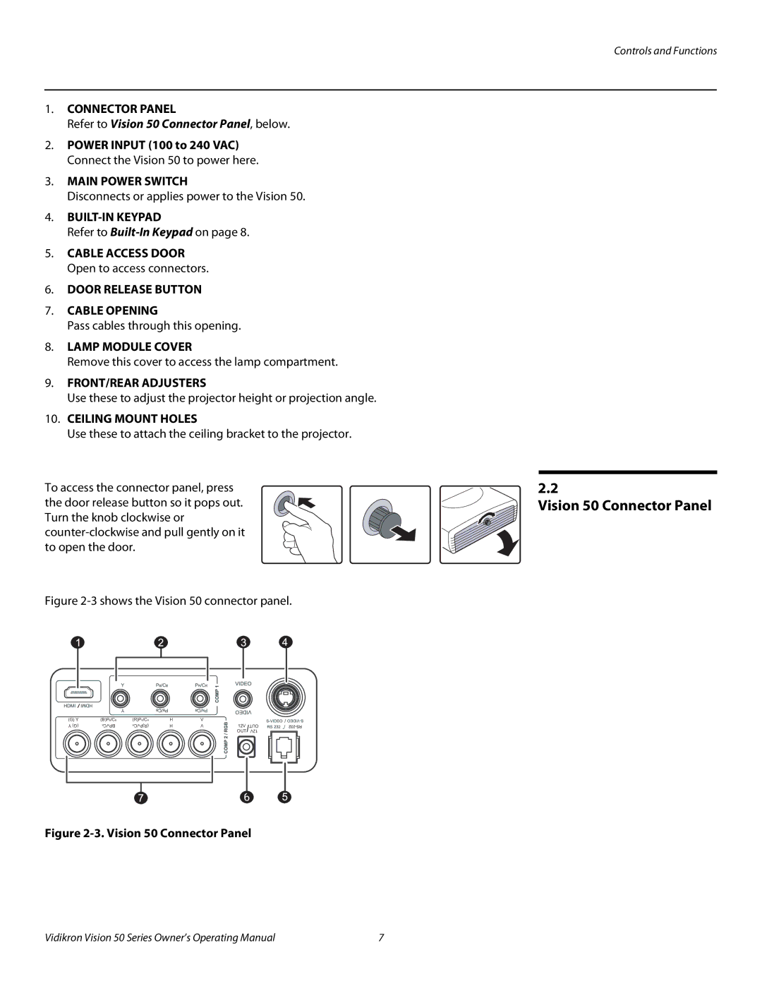
Figure 2-3 shows the Vision 50 connector panel.
(G) Y | (B)PB/CB | (R)PR/CR | H | V | 12V | OUT | ||||
Y (G) | B | /C | BP | R | /C | (R)P | H | V | ||
| B |
| R |
|
|
|
|
| ||
|
|
|
|
|
|
|
|
| OUT | 12V |
Figure 2-3. Vision 50 Connector Panel
2.2
Vision 50 Connector Panel
Vidikron Vision 50 Series Owner’s Operating Manual | 7 |