VIVOTEK
10.Tighten the screw on the fixing plate.
11.Align the three holes to mount the decoration ring.
10 |
11 |
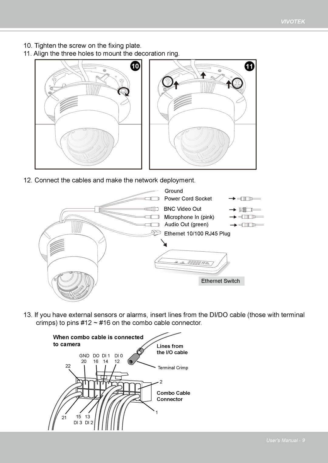
12. Connect the cables and make the network deployment.
Ground
Power Cord Socket
BNC Video Out
Microphone In (pink)
Audio Out (green)
Ethernet 10/100 RJ45 Plug
POWER | COLLISION | 1 | 2 |
|
|
|
|
|
|
| 3 | 4 | 5 |
![]()
![]()
![]() LINK
LINK ![]() RECEIVE
RECEIVE ![]()
![]() PARTITION
PARTITION
Ethernet Switch
13.If you have external sensors or alarms, insert lines from the DI/DO cable (those with terminal crimps) to pins #12 ~ #16 on the combo cable connector.
When combo cable is connected
to camera |
|
|
| Lines from |
GND | DO DI 1 | DI 0 | the I/O cable | |
| ||||
20 | 16 | 14 | 12 |
|
22 |
|
|
| Terminal Crimp |
|
|
|
| |
2
|
| Combo Cable |
|
| Connector |
|
| 1 |
21 | 15 | 13 |
| DI 3 | DI 2 |
User's Manual - 9