Managed Storage Switch
INSTALLATION&CONFIGURATION
InSpeed Model
guide
Part Number 00041363-001 Rev. A
Table of Contents
A p p e n d i x e s
Features
CHAPTER 1 Introduction
About This Guide
Overview
Fibre Channel - Arbitrated Loop
InSpeed Technology
Vixel Model 335 Installation & Configuration Guide
CHAPTER 1 Introduction
CHAPTER 2 Installation
Unpacking the Switch
Installing the Switch
Using Small Form - Factor Pluggable SFP Transceivers
Performing a Power On Systems Test
Small Form-Factor Pluggable SFP Installation
CHAPTER 2 Installation
Setting Up the Switch
Attaching Devices
Understanding the Switch’s LEDs
Power On
Figure 2-1. Switch features diagram
System LEDs
CHAPTER 2 Installation
System LEDs
Indication
Port LEDs
Port
Bypassed
Status
Activity
Cascading Switches
Figure 2-4. Cascading Switches in Overlapping Zones
Cascading with Non-Overlapping Zones
Zone Zone Zone
Figure 2-7. ACCEPTABLE Single Cascade in Zones 2-12 Only
Using the Web Manager
O v e rv i e w
Connecting to the Web Manager
CHAPTER 3 Management
CHAPTER 3 Management
Navigation
Logging On and Off
Figure 3-1. Web Manager Home Page
Configuring the Switch
Configuration Task
Resetting the Switch
Location in Web Manager
System Information Settings
Setting
Description
Figure 3-2. System Information Page
Network Settings
Figure 3-3. System Information Change Settings Page
Switch Speed
Switching Mode
Switch Identification
Blocking ARB
Downloading the Switch Configuration
Time Settings
Figure 3-5. Time Information Change Settings Page
Figure 3-4. Time Information Page
Firmware Settings
Figure 3-6. Firmware Information Page
1. Click Change Firmware Settings
Event Log Messages
1. Click Load New Firmware Image
Figure 3-7. Event Log Messages Page
FC Switch Information
Figure 3-8. FC Switch Information Page
Figure 3-9. FC Switch Information Page with Highlighted Zones
OS Information
Detection
Indication
Figure 3-10. Ordered Set Information Page
RRDY
Port Usage Information
Figure 3-11. Ordered Set Information Page with Highlighted Zones
Figure 3-12. Received Port Utilization Page
Figure 3-14. Received Port Utilization Change Settings Page
Value
Figure 3-13. Received Port Utilization Page with Highlighted Zones
Port Settings
Figure 3-15. Port Information Page
Figure 3-16. Port Information Page with Highlighted Zones
Figure 3-17. Port Information Page with Transceiver Information
Mode
Figure 3-18. Cascade Information Page
Figure 3-19. Cascade Information Page with Highlighted Zones
Policy Settings
Switch Policy
Figure 3-20. Policies Page
To update the switch’s policies
Figure 3-21. Policies Change Settings Page
Zone Settings
Figure 3-22. Overlapping Zones
Figure 3-23. Non-overlapping Zones
Figure 3-24. Zone Information Page
Overlapping Zones
Figure 3-25. Overlapping Zone 1 Information Page
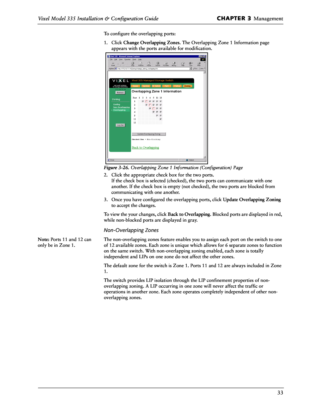
Figure 3-26. Overlapping Zone 1 Information Configuration Page
Non-Overlapping Zones
Figure 3-28. Non-Overlapping Zones Information Configuration Page
Figure 3-27. Non-Overlapping Zone Information Page
Note Ports 11 and 12 are
always in Zone
Highlighted Zones
Using the Command Line Interface CLI
Connecting to the CLI
CLI Command
Changing the Switch’s IP Parameters
Configuring Switch Information
Enabling or Disabling DHCP Requests
Managing the Firmware
Downloading New Firmware
tftp -i IPaddress PUT filename ramdisk
tftp IPaddress
Message
Action
Configuring the Trap Destination Table
Option
Changing the CLI/Web Password
Viewing Management, Policy, and Threshold Settings
Policies
Policy
Settings
Threshold Information
Options 2-Emergency, 3-Alert, 4-Critical, 5-Error, 6-Warning
Actions
Changing the Switching Mode
Command
Vixel Model 335 Installation & Configuration Guide
Displaying Ports
Vixel Model 335 Installation & Configuration Guide
Resetting the Switch
Resetting the Hardware
Resetting the Switch to Factory Default Settings
Viewing the Event Log
Changing the Switch’s Operating Speed
Overlapping Zoning Configuration
Viewing and Understanding Zoning Information
Non-Overlapping Zoning Configuration
Example noz 25,6,7,8 39,10
Reference
Technical Support
CHAPTER 4 Technical
Tro ub l e sh oo ti n g
If the switch’s Fault LED remains lit, the switch requires repair
CHAPTER 4 Technical Reference
If the Mgmt Present LED continues to blink and POST has already
Fibre Channel References
Small Form-Factor Pluggable SFP Issues
Problem
Recommended Action
Appendixes
APPENDIX A Specifications
S p e c i f i c a t i o n s
Operating Conditions
APPENDIX A Specifications
Vixel Model 335 Operating Conditions
Requirement
Commands
Console Commands
Command
General Commands
APPENDIX B CLI Console Commands
Action Commands
Command
APPENDIX C Event Messages
Event
Meaning
Action
APPENDIX C Event Messages
Vixel Model 335 Installation & Configuration Guide
APPENDIX C Event Messages
Event
Meaning
Vixel Model 335 Installation & Configuration Guide
Cross References
Loop ID-ALPA
APPENDIX D
Arbitrated Loop Physical Addresses
APPENDIX E Glossary
Enables the switch to be divided into separate environments
Index
Index