Getting connected cont.
MICROPHONE CONNECTIONS
The
NOTE: For each channel you cannot be connected to both 1/4” and XLR inputs, you must be connected to one or the other.
Connect by 1/4” mic cable (Fig. A)
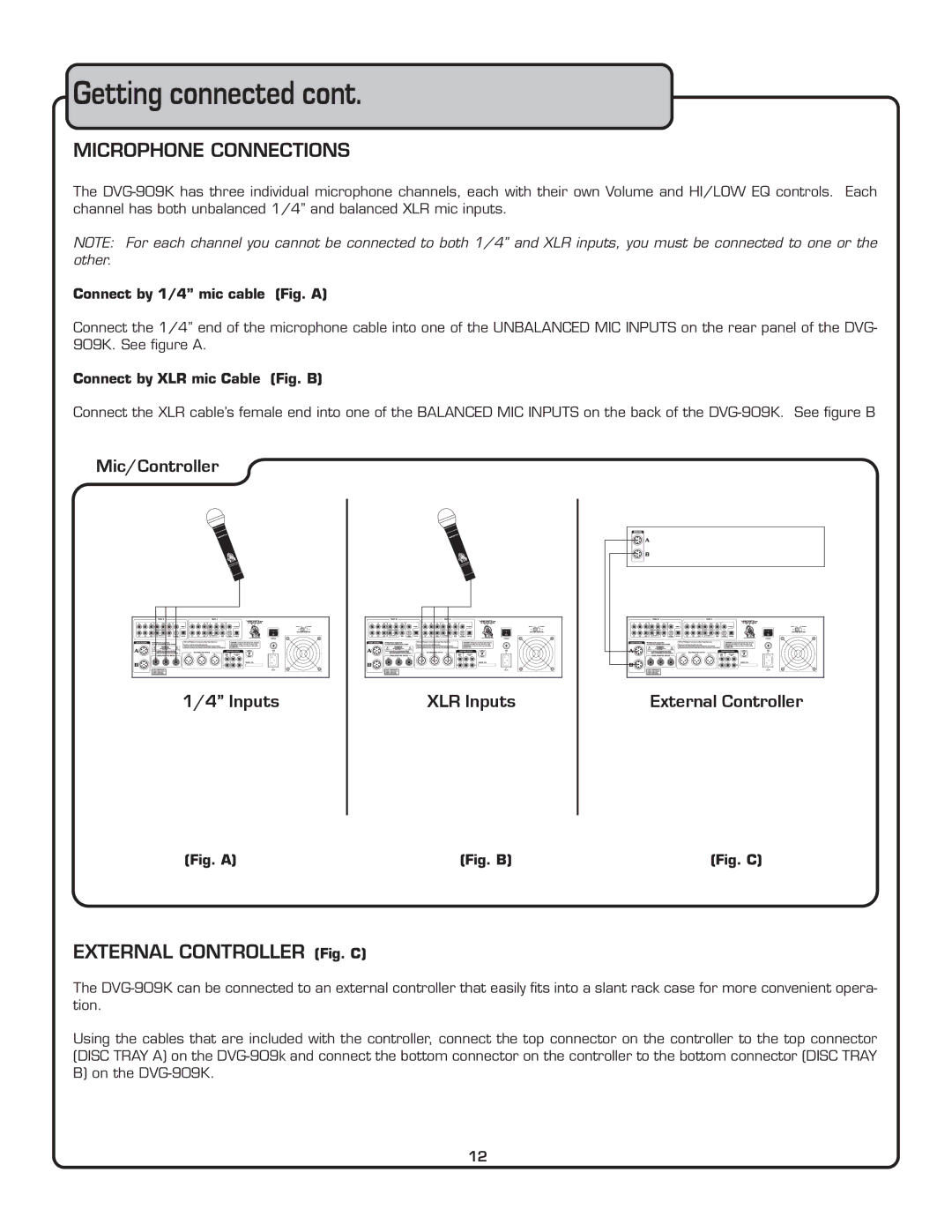
Connect the 1/4” end of the microphone cable into one of the UNBALANCED MIC INPUTS on the rear panel of the DVG- 909K. See figure A.
Connect by XLR mic Cable (Fig. B)
Connect the XLR cable’s female end into one of the BALANCED MIC INPUTS on the back of the
Mic/Controller
1/4” Inputs
(Fig. A)
XLR Inputs
(Fig. B)
External Controller
(Fig. C)
EXTERNAL CONTROLLER (Fig. C)
The
Using the cables that are included with the controller, connect the top connector on the controller to the top connector (DISC TRAY A) on the
12
