� | Side Lock | |
| ||
|
| |
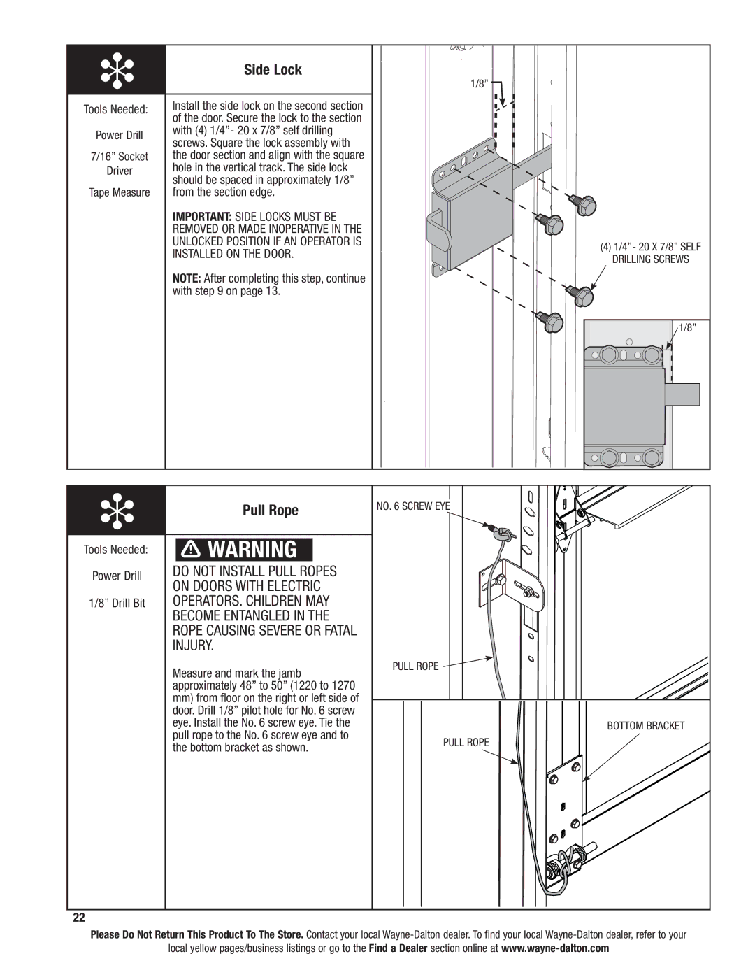
Tools Needed: | Install the side lock on the second section | |
of the door. Secure the lock to the section | ||
| ||
Power Drill | with (4) 1/4”- 20 x 7/8” self drilling | |
screws. Square the lock assembly with | ||
| ||
7/16” Socket | the door section and align with the square | |
Driver | hole in the vertical track. The side lock | |
| should be spaced in approximately 1/8” | |
Tape Measure | from the section edge. | |
| IMPORTANT: side locks must be | |
| removed or made inoperative in the | |
| unlocked position if an operator is | |
| installed on the door. | |
| NOTE: After completing this step, continue | |
| with step 9 on page 13. | |
|
|
1/8”
(4)1/4”- 20 x 7/8” self drilling screws
1/8”
� | Pull Rope | NO. 6 SCREW EYE |
| ||
Tools Needed: | WARNING |
|
Power Drill | DO NOT INSTALL PULL ROPES |
|
| ON DOORS WITH ELECTRIC |
|
1/8” Drill Bit | OPERATORS. CHILDREN MAY |
|
| BECOME ENTANGLED IN THE |
|
| ROPE CAUSING SEVERE OR FATAL |
|
| INJURY. |
|
| Measure and mark the jamb | PULL ROPE |
|
| |
| approximately 48” to 50” (1220 to 1270 |
|
| mm) from floor on the right or left side of |
|
| door. Drill 1/8” pilot hole for No. 6 screw |
|
| eye. Install the No. 6 screw eye. Tie the | BOTTOM BRACKET |
| pull rope to the No. 6 screw eye and to | PULL ROPE |
| the bottom bracket as shown. | |
|
| |
22 |
|
|
Please Do Not Return This Product To The Store. Contact your local
local yellow pages/business listings or go to the Find a Dealer section online at
