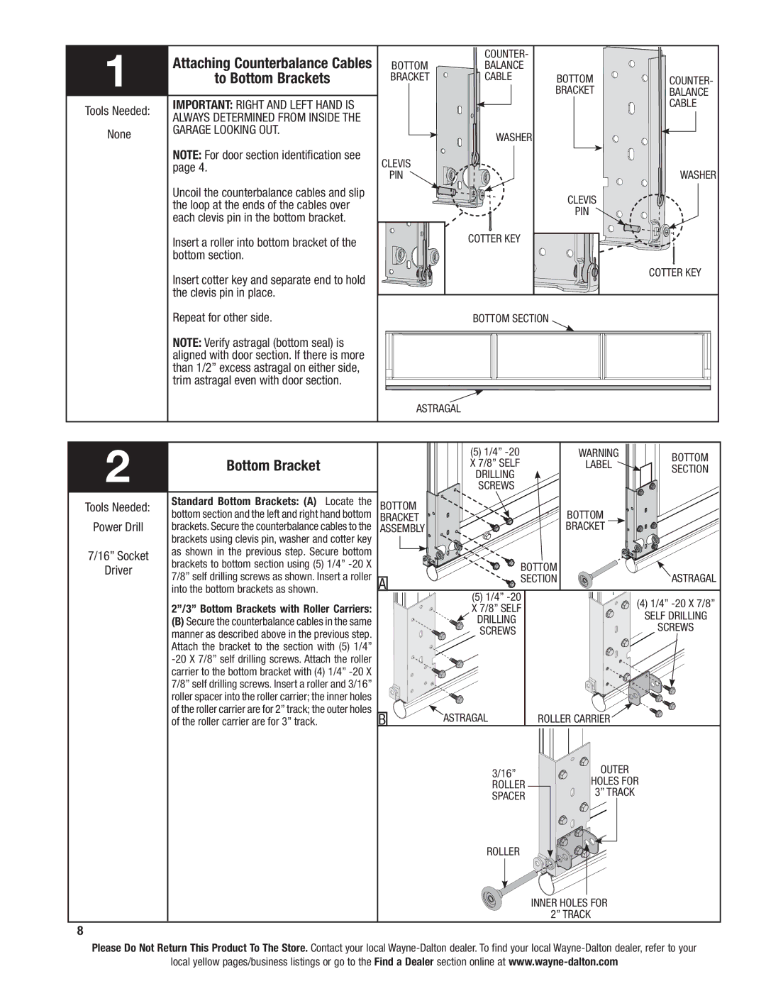
1 | Attaching Counterbalance Cables |
| counter- |
|
|
BOTTOM | balance |
|
| ||
to Bottom Brackets | BRACKET | cable | BOTTOM | counter- | |
|
|
| BRACKET | balance | |
Tools Needed: | IMPORTANT: Right and left hand is |
|
|
| cable |
always determined from inside the |
|
|
|
| |
|
|
|
|
| |
None | garage looking out. |
| Washer |
|
|
|
|
|
| ||
| NOTE: For door section identification see | clevis |
|
|
|
| page 4. |
|
| Washer | |
|
| pin |
|
| |
| Uncoil the counterbalance cables and slip |
|
| clevis |
|
| the loop at the ends of the cables over |
|
|
| |
|
|
| pin |
| |
| each clevis pin in the bottom bracket. |
|
|
| |
|
|
|
|
| |
| Insert a roller into bottom bracket of the |
| cotter key |
|
|
| bottom section. |
|
|
|
|
| Insert cotter key and separate end to hold |
|
|
| cotter key |
|
|
|
|
| |
| the clevis pin in place. |
|
|
|
|
| Repeat for other side. |
| BOTTOM SECTION |
|
|
NOTE: Verify astragal (bottom seal) is aligned with door section. If there is more than 1/2” excess astragal on either side, trim astragal even with door section.
|
|
| astragal |
|
| |
2 |
|
|
| (5) 1/4” | warning | Bottom |
Bottom Bracket |
|
| x 7/8” self | label | ||
|
| section | ||||
|
|
| drilling |
|
| |
|
|
| SCREWS |
|
| |
Tools Needed: | Standard Bottom Brackets: (A) | Locate the | BOTTOM |
| Bottom |
|
Power Drill | bottom section and the left and right hand bottom | BRACKET |
|
| ||
brackets. Secure the counterbalance cables to the | ASSEMBLY |
| Bracket |
| ||
| brackets using clevis pin, washer and cotter key |
|
|
|
| |
7/16” Socket | as shown in the previous step. Secure bottom |
|
|
|
| |
brackets to bottom section using (5) 1/4” |
| BOTTOM |
| |||
Driver |
|
| ||||
7/8” self drilling screws as shown. Insert a roller |
| astragal | ||||
| A | SECTION | ||||
| into the bottom brackets as shown. |
| (5) 1/4” |
|
| |
|
|
|
|
| (4) 1/4” | |
| 2”/3” Bottom Brackets with Roller Carriers: |
| x 7/8” self |
| ||
|
|
| SELF DRILLING | |||
| (B) Secure the counterbalance cables in the same |
| drilling |
| ||
|
|
| SCREWS | |||
| manner as described above in the previous step. |
| SCREWS |
| ||
|
|
|
| |||
| Attach the bracket to the section with (5) 1/4” |
|
|
|
| |
|
|
|
|
| ||
| carrier to the bottom bracket with (4) 1/4” |
|
|
|
| |
| 7/8” self drilling screws. Insert a roller and 3/16” |
|
|
|
| |
| roller spacer into the roller carrier; the inner holes |
|
|
|
| |
| of the roller carrier are for 2” track; the outer holes | B | astragal | Roller Carrier |
| |
| of the roller carrier are for 3” track. |
|
| |||
|
|
|
| 3/16” | outer |
|
|
|
|
| holes for | ||
|
|
|
| roller | ||
|
|
|
| 3” track |
| |
|
|
|
| spacer |
| |
|
|
|
|
|
| |
|
|
|
| Roller |
|
|
|
|
|
|
| Inner holes for |
|
|
|
|
|
| 2” track |
|
8
Please Do Not Return This Product To The Store. Contact your local
local yellow pages/business listings or go to the Find a Dealer section online at
