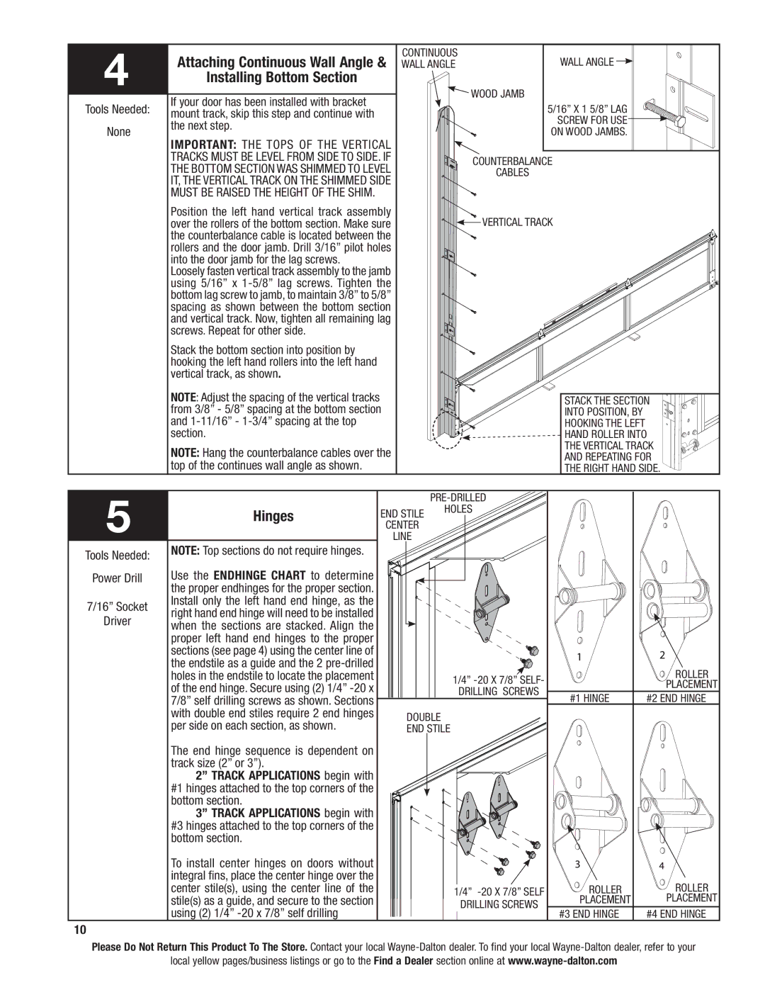
4 | Attaching Continuous Wall Angle & | continuous | Wall Angle |
| ||
| Wall Angle |
| ||||
| Installing Bottom Section |
|
|
|
|
|
| If your door has been installed with bracket |
|
| Wood Jamb |
|
|
Tools Needed: |
|
|
| 5/16” X 1 5/8” Lag |
| |
mount track, skip this step and continue with |
|
|
|
| ||
|
|
|
| screw for use |
| |
None | the next step. |
|
|
|
| |
|
|
| on wood jambs. |
| ||
Important: The tops of the vertical |
|
|
| |||
|
|
|
|
| ||
| tracks must be level from side to side. If |
| Counterbalance |
| ||
| the bottom section was shimmed to level |
|
| |||
|
| cables |
|
| ||
| it, the vertical track on the shimmed side |
|
|
|
| |
| must be raised the height of the shim. |
|
|
|
|
|
| Position the left hand vertical track assembly |
| vertical track |
| ||
| over the rollers of the bottom section. Make sure |
|
| |||
| the counterbalance cable is located between the |
|
|
|
| |
| rollers and the door jamb. Drill 3/16” pilot holes |
|
|
|
| |
| into the door jamb for the lag screws. |
|
|
|
|
|
| Loosely fasten vertical track assembly to the jamb |
|
|
|
| |
| using 5/16” x |
|
|
|
| |
| bottom lag screw to jamb, to maintain 3/8” to 5/8” |
|
|
|
| |
| spacing as shown between the bottom section |
|
|
|
| |
| and vertical track. Now, tighten all remaining lag |
|
|
|
| |
| screws. Repeat for other side. |
|
|
|
|
|
| Stack the bottom section into position by |
|
|
|
|
|
| hooking the left hand rollers into the left hand |
|
|
|
|
|
| vertical track, as shown. |
|
|
|
|
|
| NOTE: Adjust the spacing of the vertical tracks |
|
|
| Stack the section | |
| from 3/8” - 5/8” spacing at the bottom section |
|
| into position, by |
| |
| and |
|
|
| hooking the left |
|
| section. |
|
|
| hand roller into | |
| NOTE: Hang the counterbalance cables over the |
|
| the vertical track | ||
|
|
| and repeating for | |||
| top of the continues wall angle as shown. |
|
|
| the right hand side. | |
5 |
|
|
|
|
| |
Hinges | end stile | HOLES |
|
| ||
|
|
| ||||
| center |
|
|
| ||
|
| line |
|
|
| |
Tools Needed: | NOTE: Top sections do not require hinges. |
|
|
|
|
|
|
|
|
|
|
| |
Power Drill | Use the endhinge chart to determine |
|
|
|
|
|
| the proper endhinges for the proper section. |
|
|
|
|
|
7/16” Socket | Install only the left hand end hinge, as the |
|
|
|
|
|
right hand end hinge will need to be installed |
|
|
|
|
| |
Driver |
|
|
|
|
| |
when the sections are stacked. Align the |
|
|
|
|
| |
|
|
|
|
|
| |
| proper left hand end hinges to the proper |
|
|
|
|
|
| sections (see page 4) using the center line of |
|
|
|
|
|
| the endstile as a guide and the 2 |
|
|
|
| roller |
| holes in the endstile to locate the placement |
|
| 1/4” |
| |
| of the end hinge. Secure using (2) 1/4” |
|
|
| placement | |
|
|
| DRILLING SCREWS |
| ||
|
|
| #1 Hinge | #2 End Hinge | ||
| 7/8” self drilling screws as shown. Sections |
|
|
| ||
| with double end stiles require 2 end hinges |
| Double |
|
| |
| per side on each section, as shown. |
|
|
| ||
|
| End Stile |
|
| ||
The end hinge sequence is dependent on track size (2” or 3”).
2” track applications begin with #1 hinges attached to the top corners of the bottom section.
3” track applications begin with #3 hinges attached to the top corners of the bottom section.
To install center hinges on doors without |
|
|
| |
integral fins, place the center hinge over the |
|
|
| |
center stile(s), using the center line of the | 1/4” | roller | roller | |
stile(s) as a guide, and secure to the section | drilling screws | placement | placement | |
#4 End Hinge | ||||
using (2) 1/4” |
| #3 End Hinge |
10
Please Do Not Return This Product To The Store. Contact your local
local yellow pages/business listings or go to the Find a Dealer section online at