9300 specifications
The Wayne-Dalton 9300 is a high-quality insulated steel garage door renowned for its durability, energy efficiency, and aesthetic appeal. Designed to meet a range of residential needs, the 9300 series combines performance with style, making it a popular choice among homeowners.One of the standout features of the Wayne-Dalton 9300 is its construction. The door consists of a robust, 2-inch thick panel that is filled with high-density polystyrene insulation. This insulation not only provides excellent thermal performance but also contributes to the door's overall strength. With an R-value of up to 13.4, the 9300 series helps maintain a comfortable temperature in the garage while reducing energy costs for heating or cooling adjacent spaces.
In terms of design flexibility, the Wayne-Dalton 9300 is available in a variety of colors and finishes, allowing homeowners to match their garage doors to their home’s exterior. The door is constructed using steel that is pre-painted and baked with a tough finish to resist fading, chipping, and denting. Homeowners can choose from various contemporary and traditional styles, ensuring a perfect fit for any architectural design.
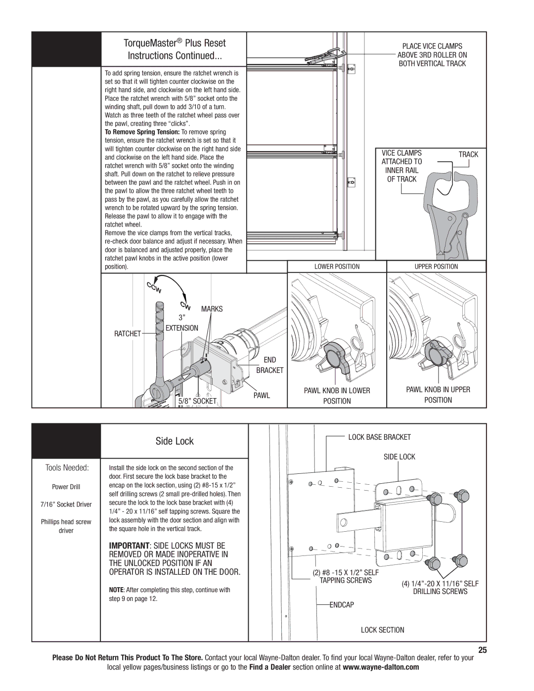
The Wayne-Dalton 9300 also incorporates advanced technology, such as the TorqueMaster® lifting system. This innovative system provides a torsion spring lift that is safely contained within the door's structure, reducing the risk of injury and ensuring smooth operation. Additionally, the 9300 series comes equipped with high-quality weather seals that protect against wind, rain, and snow, enhancing the door’s performance in various weather conditions.
Moreover, the 9300 series emphasizes safety features, including pinch-resistant design, which helps to prevent fingers from getting caught during operation. The doors also utilize high-performance rollers and sturdy hardware to ensure reliable, quiet, and long-lasting operation.
In summary, the Wayne-Dalton 9300 is an excellent choice for those seeking a durable, energy-efficient, and stylish garage door. With its advanced insulation technology, variety of design options, innovative lifting system, and emphasis on safety, the 9300 series stands out as a top contender in the market for residential garage doors. It offers homeowners peace of mind while enhancing the overall curb appeal of their property.

