GOLD CGi
11c Troubleshooting — control module lights (cont.)
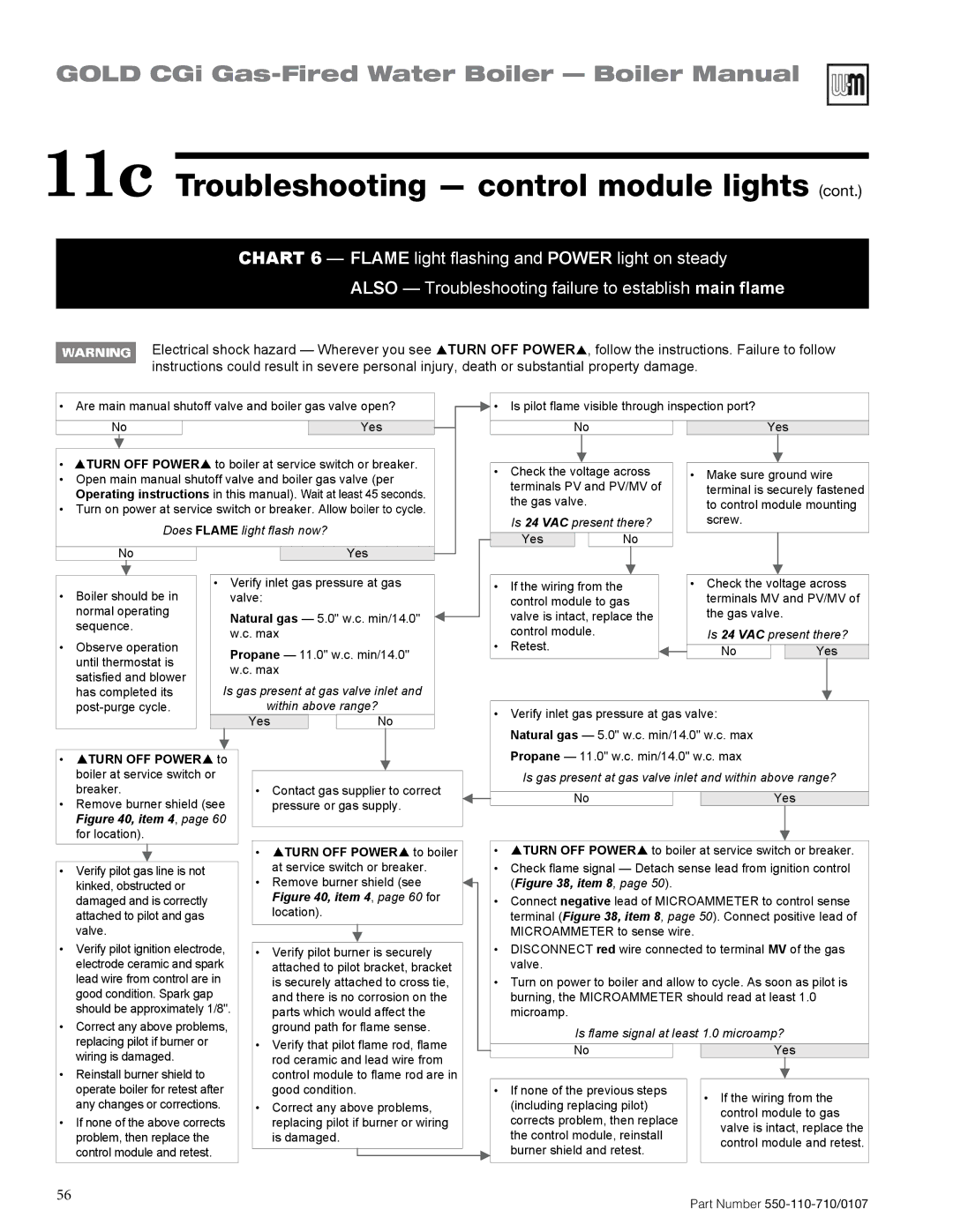
CHART 6 — FLAME light flashing and POWER light on steady
ALSO — Troubleshooting failure to establish main flame
|
|
|
|
|
| Electrical shock hazard — Wherever you see TURN OFF POWER | , follow the instructions. Failure to follow | |||||||||||||||||||||||||||||||||||
|
|
|
|
| ||||||||||||||||||||||||||||||||||||||
|
|
|
|
|
| instructions could result in severe personal injury, death or substantial property damage. |
|
|
|
|
|
| ||||||||||||||||||||||||||||||
|
|
|
|
|
|
|
|
|
|
| ||||||||||||||||||||||||||||||||
|
|
|
|
|
|
|
|
|
|
|
|
|
|
|
|
|
|
|
|
|
|
|
|
|
|
|
|
|
|
|
|
|
|
|
| |||||||
• Are main manual shutoff valve and boiler gas valve open? |
|
|
|
|
|
| • | Is pilot flame visible through inspection port? |
|
| ||||||||||||||||||||||||||||||||
|
|
|
|
|
|
|
| |||||||||||||||||||||||||||||||||||
|
|
|
|
|
|
|
|
|
|
|
|
|
|
|
|
|
|
|
|
|
|
|
|
|
|
|
|
|
|
|
|
|
|
|
|
|
|
|
|
|
| |
| No |
|
|
|
|
|
|
|
|
|
|
|
| Yes |
|
|
|
| No |
|
| Yes |
|
| ||||||||||||||||||
|
|
|
|
|
|
|
|
|
|
|
|
|
|
|
|
|
|
|
|
|
| |||||||||||||||||||||
|
|
|
|
|
|
|
|
|
|
|
|
|
|
|
|
|
|
|
|
|
|
|
|
|
|
|
|
|
|
|
|
|
|
|
|
|
|
|
|
|
|
|
• | TURN OFF POWER | to boiler at service switch or breaker. |
|
|
|
|
|
|
|
|
|
|
|
|
|
|
|
|
|
|
|
|
|
| ||||||||||||||||||
|
|
|
|
|
| • | Check the voltage across |
| • | Make sure ground wire | ||||||||||||||||||||||||||||||||
• Open main manual shutoff valve and boiler gas valve (per |
|
|
|
|
|
|
| |||||||||||||||||||||||||||||||||||
|
|
|
|
|
|
| terminals PV and PV/MV of |
|
| terminal is securely fastened | ||||||||||||||||||||||||||||||||
| Operating instructions in this manual). |
|
|
|
|
|
|
|
|
| ||||||||||||||||||||||||||||||||
|
|
|
|
|
|
|
| the gas valve. |
|
|
|
|
|
| to control module mounting | |||||||||||||||||||||||||||
• Turn on power at service switch or breaker. A |
|
|
|
|
|
|
|
|
|
|
|
|
| |||||||||||||||||||||||||||||
|
|
|
|
|
|
| Is 24 VAC present there? |
|
| screw. |
|
| ||||||||||||||||||||||||||||||
|
|
|
|
|
| Does FLAME light flash now? |
|
|
|
|
|
|
|
|
|
|
| |||||||||||||||||||||||||
|
|
|
|
|
|
|
|
|
|
|
|
| Yes |
|
| No |
|
|
|
|
|
|
|
| ||||||||||||||||||
|
|
|
|
|
|
|
|
|
|
|
|
|
|
|
|
|
|
|
|
|
|
|
|
|
|
|
|
|
|
|
|
|
|
|
|
|
| |||||
| No |
|
|
|
|
|
|
|
|
|
| Yes |
|
|
|
|
|
|
|
|
|
|
|
|
|
|
|
|
|
|
|
|
|
| ||||||||
|
|
|
|
|
|
|
|
|
|
|
|
|
|
|
|
|
|
|
|
|
|
|
|
|
|
|
|
|
|
|
| |||||||||||
|
|
|
|
|
|
|
|
|
|
|
|
|
|
|
|
|
|
|
|
|
|
|
|
|
|
|
|
|
|
|
|
|
|
|
|
|
|
|
|
|
|
|
|
|
|
|
|
|
|
|
|
|
|
|
|
|
|
|
|
|
|
|
|
|
|
|
|
|
|
|
|
|
|
|
|
|
|
|
|
|
|
|
|
|
|
• Boiler should be in |
| • Verify inlet gas pressure at gas |
|
|
|
|
|
| • | If the wiring from the |
|
| • | Check the voltage across | ||||||||||||||||||||||||||||
|
|
| valve: |
|
|
|
|
|
|
|
|
|
|
|
|
|
| control module to gas |
|
|
| terminals MV and PV/MV of | ||||||||||||||||||||
| normal operating |
|
|
| Natural gas — 5.0" w.c. min/14.0" |
|
|
|
|
|
|
| valve is intact, replace the |
|
|
|
| the gas valve. |
|
| ||||||||||||||||||||||
| sequence. |
|
|
|
|
|
|
|
|
|
|
|
|
|
| |||||||||||||||||||||||||||
|
|
|
| w.c. max |
|
|
|
|
|
|
| control module. |
|
|
|
| Is 24 VAC present there? | |||||||||||||||||||||||||
|
|
|
|
|
|
|
|
|
|
|
|
|
|
|
|
|
|
| ||||||||||||||||||||||||
• | Observe operation |
|
|
|
|
|
|
|
|
|
|
|
|
|
|
|
|
|
|
| • | Retest. |
|
|
|
|
|
|
|
|
|
|
|
| ||||||||
|
|
| Propane — 11.0" w.c. min/14.0" |
|
|
|
|
|
|
|
|
|
|
|
| No |
|
|
| Yes | ||||||||||||||||||||||
| until thermostat is |
|
|
|
|
|
|
|
|
|
|
|
|
|
|
|
|
|
|
|
| |||||||||||||||||||||
|
|
|
| w.c. max |
|
|
|
|
|
|
|
|
|
|
|
|
|
|
|
|
|
|
|
|
|
| ||||||||||||||||
| satisfied and blower |
|
|
|
|
|
|
|
|
|
|
|
|
|
|
|
|
|
|
|
|
|
|
| ||||||||||||||||||
|
| Is gas present at gas valve inlet and |
|
|
|
|
|
|
|
|
|
|
|
|
|
|
|
|
|
|
|
|
|
| ||||||||||||||||||
| has completed its |
|
|
|
|
|
|
|
|
|
|
|
|
|
|
|
|
|
|
|
|
| ||||||||||||||||||||
|
|
|
|
|
|
|
|
|
|
|
|
|
|
|
|
|
|
|
|
|
|
|
| |||||||||||||||||||
|
|
|
|
|
|
| within above range? |
|
|
|
|
|
|
|
|
|
|
|
|
|
|
|
|
|
|
|
| |||||||||||||||
|
|
|
|
|
|
|
|
|
|
|
|
| • Verify inlet gas pressure at gas valve: |
|
| |||||||||||||||||||||||||||
|
|
|
|
|
|
|
|
|
|
|
| Yes |
|
|
|
| No |
|
|
|
|
|
|
|
| |||||||||||||||||
|
|
|
|
|
|
|
|
|
|
|
|
|
|
|
|
|
|
|
|
| Natural gas — 5.0" w.c. min/14.0" w.c. max |
|
| |||||||||||||||||||
|
|
|
|
|
|
|
|
|
|
|
|
|
|
|
|
|
|
|
|
|
|
|
|
|
|
|
|
|
| |||||||||||||
|
|
|
|
|
|
|
|
|
|
|
|
|
|
|
|
|
|
|
|
| Propane — 11.0" w.c. min/14.0" w.c. max |
|
| |||||||||||||||||||
• | TURN OFF POWER | to |
|
|
|
|
|
|
|
|
|
|
|
|
|
|
|
|
|
|
| |||||||||||||||||||||
|
|
|
|
|
|
|
|
|
|
|
|
|
|
|
|
|
|
| ||||||||||||||||||||||||
| boiler at service switch or |
|
|
|
|
|
|
|
|
|
|
|
|
|
|
|
|
| Is gas present at gas valve inlet and within above range? | |||||||||||||||||||||||
|
|
|
|
|
|
|
|
|
|
|
|
|
|
|
|
|
| |||||||||||||||||||||||||
| breaker. |
|
|
|
| • |
| Contact gas supplier to correct |
|
|
|
|
|
|
|
|
|
|
|
|
|
|
|
|
|
|
| |||||||||||||||
• Remove burner shield (see |
|
|
|
| pressure or gas supply. |
|
|
|
| No |
|
|
| Yes |
|
| ||||||||||||||||||||||||||
|
|
|
|
|
|
|
|
|
|
|
|
| ||||||||||||||||||||||||||||||
| Figure 40, item 4, page 60 |
|
|
|
|
|
|
|
|
|
|
|
|
|
|
|
|
|
|
|
|
|
|
|
|
|
|
|
|
|
|
|
| |||||||||
| for location). |
|
|
|
|
|
|
|
|
|
|
|
|
|
|
|
|
|
|
|
|
|
|
|
|
|
|
|
|
|
|
|
|
|
| |||||||
|
|
|
|
|
|
|
|
|
|
|
|
| • |
|
| TURN OFF POWER to boiler |
|
|
| • | TURN OFF POWER to boiler at service switch or breaker. | |||||||||||||||||||||
|
|
|
|
|
|
|
|
|
|
|
|
|
|
|
|
|
| |||||||||||||||||||||||||
|
|
|
|
|
|
|
| at service switch or breaker. |
|
|
| • | Check flame signal — Detach sense lead from ignition control | |||||||||||||||||||||||||||||
• Verify pilot gas line is not |
|
|
|
|
|
|
|
|
| |||||||||||||||||||||||||||||||||
| kinked, obstructed or |
|
|
|
| • |
| Remove burner shield (see |
|
|
|
| (Figure 38, item 8, page 50). |
|
|
|
|
|
|
| ||||||||||||||||||||||
|
|
|
|
|
|
|
|
|
|
|
|
|
|
|
|
| ||||||||||||||||||||||||||
| damaged and is correctly |
|
|
|
|
|
| Figure 40, item 4, page 60 for |
|
|
| • | Connect negative lead of MICROAMMETER to control sense | |||||||||||||||||||||||||||||
| attached to pilot and gas |
|
|
|
|
|
| location). |
|
|
|
| terminal (Figure 38, item 8, page 50). Connect positive lead of | |||||||||||||||||||||||||||||
| valve. |
|
|
|
|
|
|
|
|
|
|
|
|
|
|
|
|
|
|
| MICROAMMETER to sense wire. |
|
|
|
|
|
| |||||||||||||||
|
|
|
|
|
|
|
|
|
|
|
|
|
|
|
|
|
|
|
|
|
|
|
|
|
| |||||||||||||||||
• Verify pilot ignition electrode, |
|
| • |
| Verify pilot burner is securely |
|
|
| • | DISCONNECT red wire connected to terminal MV of the gas | ||||||||||||||||||||||||||||||||
| electrode ceramic and spark |
|
|
|
| attached to pilot bracket, bracket |
|
|
|
| valve. |
|
|
|
|
|
|
|
|
|
|
|
| |||||||||||||||||||
| lead wire from control are in |
|
|
|
| is securely attached to cross tie, |
|
|
| • | Turn on power to boiler and allow to cycle. As soon as pilot is | |||||||||||||||||||||||||||||||
| good condition. Spark gap |
|
|
|
|
|
| and there is no corrosion on the |
|
|
|
| burning, the MICROAMMETER should read at least 1.0 | |||||||||||||||||||||||||||||
| should be approximately 1/8". |
|
|
| parts which would affect the |
|
|
|
| microamp. |
|
|
|
|
|
|
|
|
|
|
|
| ||||||||||||||||||||
• Correct any above problems, |
|
|
|
| ground path for flame sense. |
|
|
|
|
| Is flame signal at least 1.0 microamp? |
|
| |||||||||||||||||||||||||||||
| replacing pilot if burner or |
|
|
|
| • |
| Verify that pilot flame rod, flame |
|
|
|
|
|
|
| |||||||||||||||||||||||||||
| wiring is damaged. |
|
|
|
|
|
| rod ceramic and lead wire from |
|
|
|
| No |
|
|
| Yes |
|
| |||||||||||||||||||||||
|
|
|
|
|
|
|
|
|
|
|
|
|
|
|
| |||||||||||||||||||||||||||
|
|
|
|
|
|
|
|
|
|
|
|
|
|
|
|
|
|
|
|
|
|
|
|
|
| |||||||||||||||||
• Reinstall burner shield to |
|
|
|
|
|
| control module to flame rod are in |
|
|
|
|
|
|
|
|
|
|
|
|
|
|
|
|
|
|
| ||||||||||||||||
| operate boiler for retest after |
|
|
|
| good condition. |
|
|
| • | If none of the previous steps |
| • If the wiring from the | |||||||||||||||||||||||||||||
| any changes or corrections. |
|
| • |
| Correct any above problems, |
|
|
|
| (including replacing pilot) |
| ||||||||||||||||||||||||||||||
|
|
|
|
|
|
|
|
| control module to gas | |||||||||||||||||||||||||||||||||
• If none of the above corrects |
|
|
|
| replacing pilot if burner or wiring |
|
|
|
| corrects problem, then replace |
| |||||||||||||||||||||||||||||||
|
|
|
|
|
|
|
|
| valve is intact, replace the | |||||||||||||||||||||||||||||||||
| problem, then replace the |
|
|
|
|
|
| is damaged. |
|
|
|
| the control module, reinstall |
| ||||||||||||||||||||||||||||
|
|
|
|
|
|
|
|
|
|
|
| control module and retest. | ||||||||||||||||||||||||||||||
| control module and retest. |
|
|
|
|
|
|
|
|
|
|
|
|
|
|
|
|
|
|
| burner shield and retest. |
| ||||||||||||||||||||
|
|
|
|
|
|
|
|
|
|
|
|
|
|
|
|
|
|
|
|
|
|
|
|
|
|
| ||||||||||||||||
|
|
|
|
|
|
|
|
|
|
|
|
|
|
|
|
|
|
|
|
|
|
|
|
|
|
| ||||||||||||||||
56 | Part Number |
|