4. Hardware Installation
4.1. Connecting Power to the APS Unit
The
CAUTION:
•Before attempting to install this unit, please review the warnings and cautions listed at the front of the user's guide.
•This device should only be operated with the type of power source indicated on the instrument nameplate. If you are not sure of the type of power service available, please contact your local power company.
4.1.1.AC Powered Units
Plug the power cable (supplied with the unit) into the receptacle on the back panel, and then connect the power cable to an appropriate, grounded outlet. The APS features a self adjusting power supply that automatically adapts to power supplies between 100 and 240 VAC. Press the Power Switch ON. The ON LED should light and the RDY LED should begin to flash.
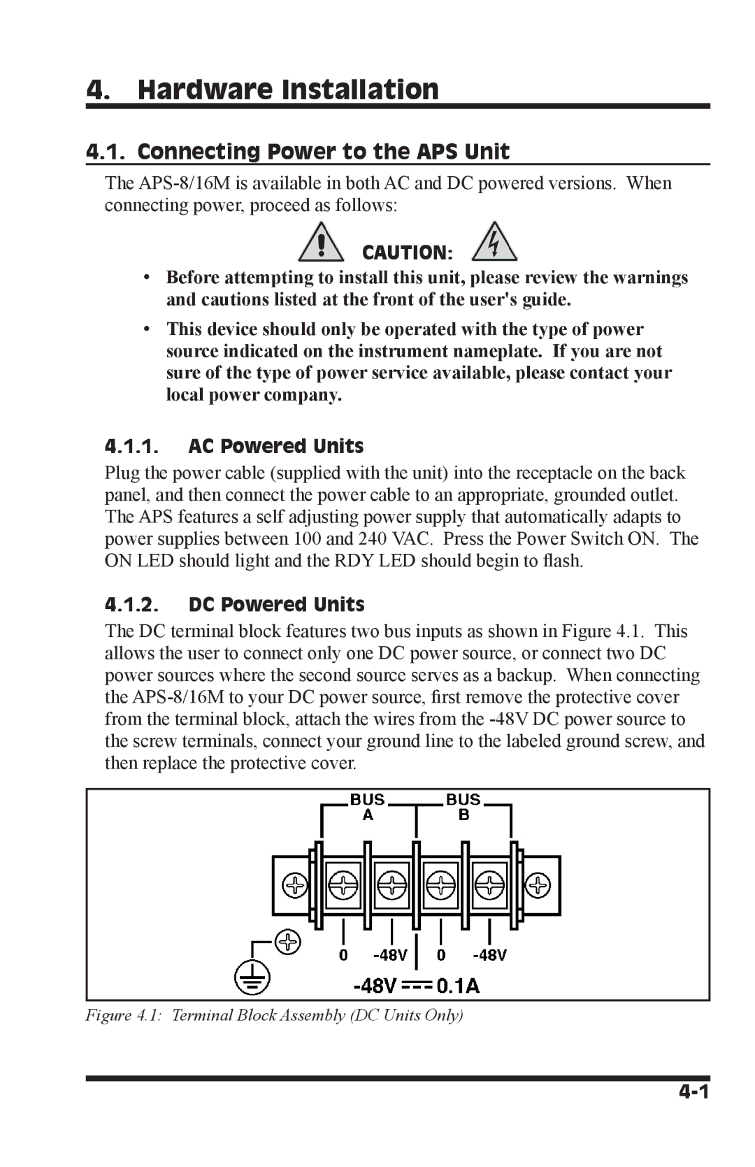
4.1.2.DC Powered Units
The DC terminal block features two bus inputs as shown in Figure 4.1. This allows the user to connect only one DC power source, or connect two DC power sources where the second source serves as a backup. When connecting the