| Hardware Installation |
|
|
|
|
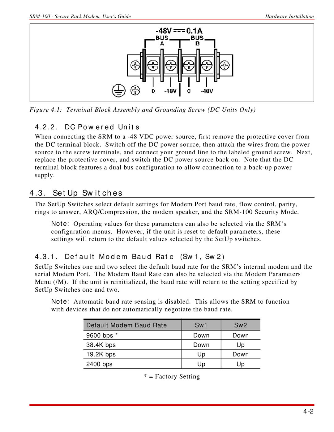
Figure 4.1: Terminal Block Assembly and Grounding Screw (DC Units Only)
4.2.2. DC Powered Units
When connecting the SRM to a
4.3. SetUp Switches
The SetUp Switches select default settings for Modem Port baud rate, flow control, parity, rings to answer, ARQ/Compression, the modem speaker, and the
Note: Operating values for these parameters can also be selected via the SRM’s configuration menus. However, if the unit is reset to default parameters, these settings will return to the default values selected by the SetUp switches.
4.3.1. Default Modem Baud Rate (Sw1, Sw2)
SetUp Switches one and two select the default baud rate for the SRM’s internal modem and the serial Modem Port. The Modem Baud Rate can also be selected via the Modem Parameters Menu (/M). If the unit is reinitialized, the baud rate will return to the setting specified by SetUp Switches one and two.
Note: Automatic baud rate sensing is disabled. This allows the SRM to function with devices that do not automatically negotiate the baud rate.
Default Modem Baud Rate | Sw1 | Sw2 |
9600 bps * | Down | Down |
38.4K bps | Down | Up |
|
|
|
19.2K bps | Up | Down |
|
|
|
2400 bps | Up | Up |
|
|
|
* = Factory Setting