Table of Contents | |
|
|
|
|
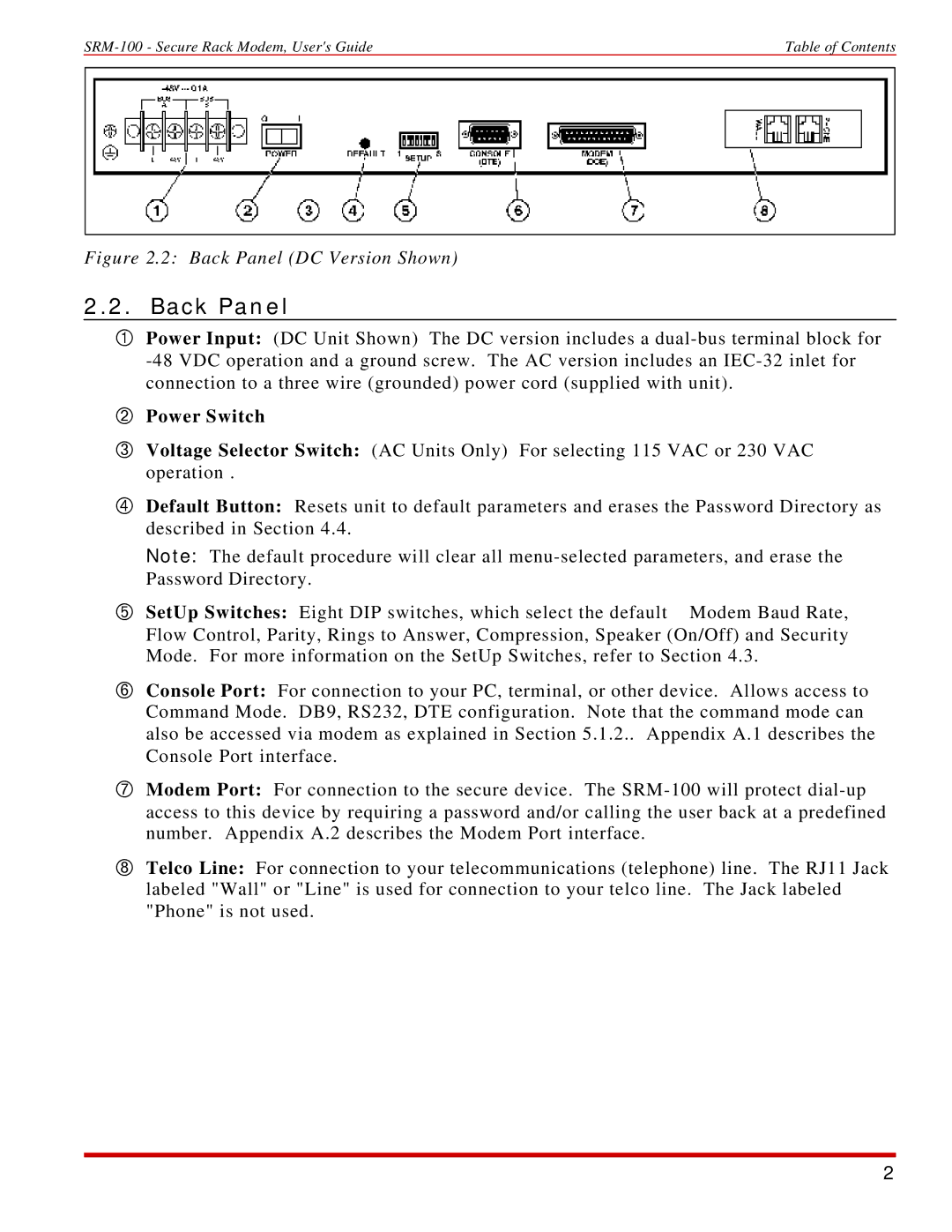
Figure 2.2: Back Panel (DC Version Shown)
2.2.Back Panel
ÀPower Input: (DC Unit Shown) The DC version includes a
ÁPower Switch
ÂVoltage Selector Switch: (AC Units Only) For selecting 115 VAC or 230 VAC operation .
ÃDefault Button: Resets unit to default parameters and erases the Password Directory as described in Section 4.4.
Note: The default procedure will clear all
Ä SetUp Switches: Eight DIP switches, which select the default Modem Baud Rate, Flow Control, Parity, Rings to Answer, Compression, Speaker (On/Off) and Security Mode. For more information on the SetUp Switches, refer to Section 4.3.
ÅConsole Port: For connection to your PC, terminal, or other device. Allows access to Command Mode. DB9, RS232, DTE configuration. Note that the command mode can also be accessed via modem as explained in Section 5.1.2.. Appendix A.1 describes the Console Port interface.
ÆModem Port: For connection to the secure device. The
ÇTelco Line: For connection to your telecommunications (telephone) line. The RJ11 Jack labeled "Wall" or "Line" is used for connection to your telco line. The Jack labeled "Phone" is not used.
2