REMOVING THE
CENTRAL CONTROL UNIT
AND PRESSURE SWITCH
The Central Control Unit is a single assembly and does not contain any serviceable parts. It can be removed by lifting the top plastic tabs securing it to the back cabinet frame and sliding it towards the front of the washer. (Fig.
Tabs
Fig.
To remove the pressure switch, first remove the wiring harness retainer from the side of the cabi- net. (Fig.
Wiring Harness
Retainer
Fig.
Then disconnect the wiring harness connectors and the pressure hose and turn the pressure switch counterclockwise to release it from the cabinet. (Fig.
Pressure Switch
Fig.
REMOVING THE DRIVE MOTOR
The drive motor can be removed once the back panel has been removed.
Twelve screws secure the back panel to the washer. Remove the 12 screws and remove the back panel. Remove the Drive Belt.
Disconnect the wiring harness connectors and ground wires from the drive motor terminals. Push the wiring harness tie from the motor mounting bracket.
Remove the mounting bolt securing the motor to the tub. (Fig.
Mounting
Bolt
Fig.
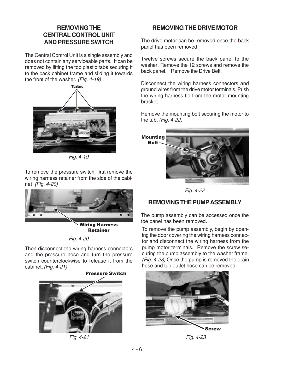
REMOVING THE PUMP ASSEMBLY
The pump assembly can be accessed once the toe panel has been removed.
To remove the pump assembly, begin by open- ing the door covering the wiring harness connec- tor and disconnect the wiring harness from the pump motor terminals. Remove the screw se- curing the pump assembly to the washer frame. (Fig.
![]() Screw
Screw
Fig.
4 - 6