Sales Demo Mode
The Sales Demo mode is activated by pressing:
SOAK - WATER TEMP - SOAK - WATER TEMP
within five (5) seconds. “Sd” should be displayed in the
If the lid is opened during this cycle, the Peekaboo function will be active. This cycle should not require the lid switch to be opened afterwards to run another cycle, (i.e. no “LS” check).
PHASE | STEP | DESCRIPTION OF | NOTES | WATER | DISPENSER | COMMENT | PUMP | DRIVE | DRIVE | DURATION |
|
| SEQUENCE |
| TEMP |
|
| MOTOR | MOTOR | MOTOR | (SEC) |
|
|
|
|
|
|
| ACTION | ACTION | SPEED |
|
|
|
|
|
|
|
|
|
|
|
|
DIAGNOSTIC | 1 | NUTATE 150 |
| OFF | OFF |
| OFF | NUTATE | 150 | 8 |
| 2 | SPIN 60 |
| OFF | OFF |
| OFF | SPIN | 60 | 15 |
| 3 | NUTATE 150 |
| OFF | OFF |
| OFF | NUTATE | 150 | 5 |
| 4 | NUTATE 225 |
| OFF | OFF |
| OFF | NUTATE | 225 | 5 |
| 5 | NUTATE 250 |
| OFF | OFF |
| OFF | NUTATE | 250 | 5 |
| 6 | NUTATE 275 |
| OFF | OFF |
| OFF | NUTATE | 275 | 5 |
| 7 | NUTATE 300 |
| OFF | OFF |
| OFF | NUTATE | 300 | 5 |
| 8 | SPIN 800 |
| OFF | OFF |
| OFF | SPIN | 800 | 60 |
|
| RETURN TO STANDBY |
| OFF | OFF |
| OFF | OFF |
| 1:48 |
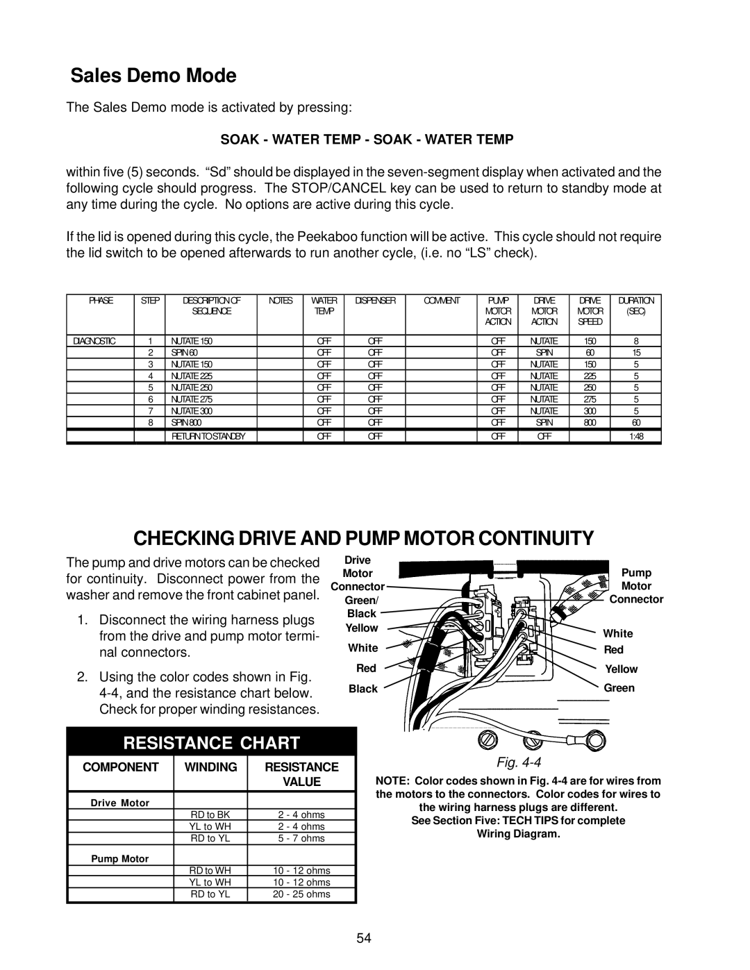
CHECKING DRIVE AND PUMP MOTOR CONTINUITY
The pump and drive motors can be checked for continuity. Disconnect power from the washer and remove the front cabinet panel.
1.Disconnect the wiring harness plugs from the drive and pump motor termi- nal connectors.
2.Using the color codes shown in Fig.
Drive
Motor
Connector
Green/
Black ![]()
Yellow
White
Red
Black
Pump
Motor
Connector
White
Red
Yellow
Green
RESISTANCE CHART
COMPONENT | WINDING | RESISTANCE | |
|
| VALUE | |
|
|
|
|
Drive Motor |
|
|
|
| RD to BK | 2 | - 4 ohms |
| YL to WH | 2 | - 4 ohms |
| RD to YL | 5 | - 7 ohms |
Pump Motor |
|
|
|
| RD to WH | 10 | - 12 ohms |
| YL to WH | 10 | - 12 ohms |
| RD to YL | 20 | - 25 ohms |
|
|
|
|
Fig.
NOTE: Color codes shown in Fig.
See Section Five: TECH TIPS for complete
Wiring Diagram.
54