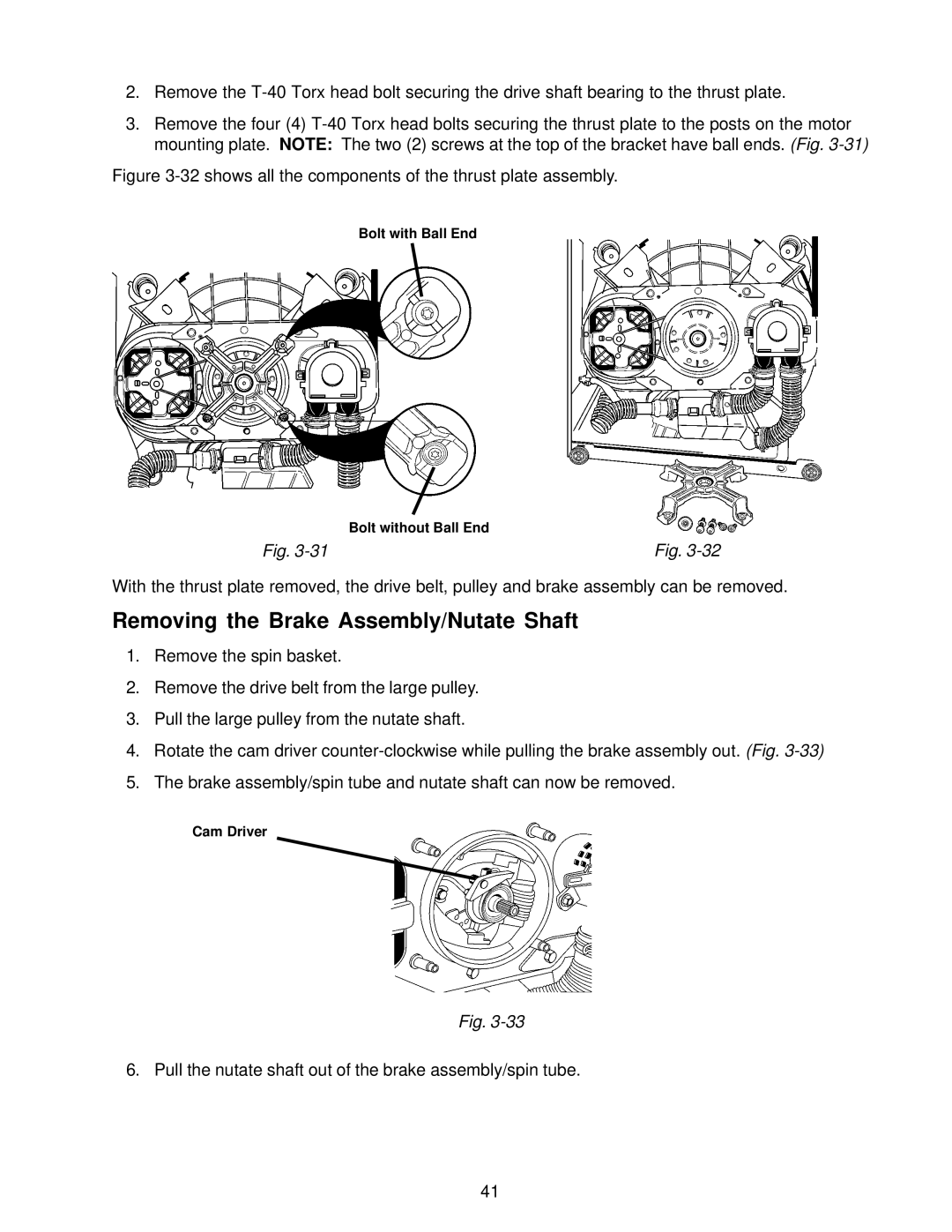
2.Remove the
3.Remove the four (4)
Figure 3-32 shows all the components of the thrust plate assembly.
Bolt with Ball End
| Bolt without Ball End |
Fig. | Fig. |
With the thrust plate removed, the drive belt, pulley and brake assembly can be removed.
Removing the Brake Assembly/Nutate Shaft
1.Remove the spin basket.
2.Remove the drive belt from the large pulley.
3.Pull the large pulley from the nutate shaft.
4.Rotate the cam driver
5.The brake assembly/spin tube and nutate shaft can now be removed.
Cam Driver
Fig.
6. Pull the nutate shaft out of the brake assembly/spin tube.
41
