5.Connect cutter driveline to tractor PTO shaft, making sure the
6.Remove parking jack from the tongue and attach it to the storage post on the front of the cutter.
7.Adjust
8.Attach drive shaft shield to bearing housing using two 3/8 x 1 cap screws and 3/8 lock washers.
Hydraulic Connection
1.Inspect hydraulic hoses to ensure they are in good condition.
2.Clean the fittings before connecting them to the tractor hydraulic ports.
3.Attach the hydraulic hose from the cutter to the tractor.
4.Route the hose through the hose holder on H- frame and be sure the hose can slide freely in the holder. Do not allow hose slack to drag on the ground or become caught on tractor protrusions.
5.From the operator position, start tractor and raise and lower deck several times to purge trapped air from the hydraulic cylinder.
Interference Check
1.Be sure that tractor
2.Check for
3.Contact between tractor lift links and cutter parts can cause damage, especially when turning.
Turning Limits for Optional CV Driveline
You must not exceed a turning angle of 80 degrees at the head of the Constant Velocity driveline or damage will occur.
To check for potential excessive turn angle:
1.Disconnect driveline from tractor, start engine and turn as far right or left as possible.
2.Shut engine off, set parking brake, remove key, and try to connect CV driveline to tractor. If it cannot be connected, the angle is too severe.
3.Restart engine and straighten angle slightly. Repeat step 2 until driveline can be connected.
The point at which the driveline can be connected is the maximum turn that should be made.
CONNECT CUTTER TO TRACTOR (MOUNTED & SEMI-MOUNTED)
Tractor Adjustments
Before attaching tractor to cutter, install sway blocks or sway chains, or adjust stabilizer bars. Refer to the trac- tor operator's manual for instructions.
Install tractor front end weights as recommended by the tractor manufacturer to provide 20% of weight on front wheels.
A minimum 20% of tractor and equipment weight must be on the tractor front wheels when attachments are in transport position. Without this weight, tractor could tip over, causing personal injury or death. The weight may be attained with front wheel weights, ballast in tires or front tractor weights. Weigh the tractor and equipment. Do not estimate.
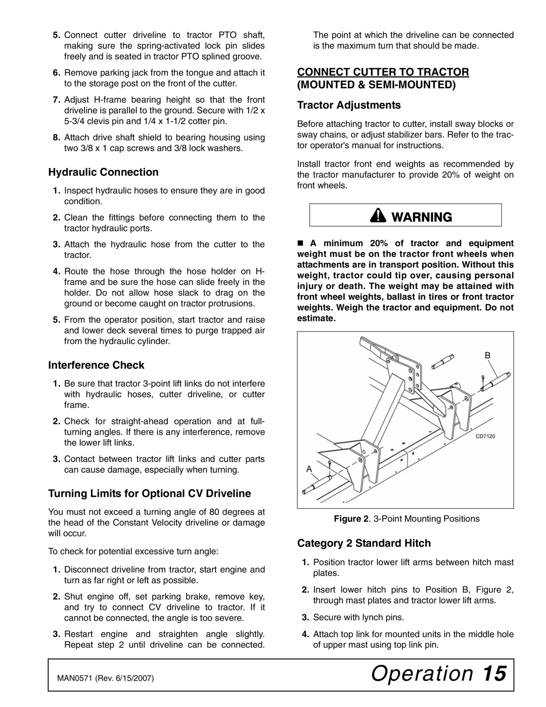
Figure 2. 3-Point Mounting Positions
Category 2 Standard Hitch
1.Position tractor lower lift arms between hitch mast plates.
2.Insert lower hitch pins to Position B, Figure 2, through mast plates and tractor lower lift arms.
3.Secure with lynch pins.
4.Attach top link for mounted units in the middle hole of upper mast using top link pin.
MAN0571 (Rev. 6/15/2007) | Operation 15 |
|
|