BLADE SERVICING
Removing Blades (Figure 11)
NOTICE
■If blade pin (12) is seized in crossbar and extreme force will be needed to remove it, support crossbar from below to prevent gearbox damage.
1.Disconnect driveline from tractor PTO.
2.Open blade access cover and align crossbar (8) with blade access hole in the cutter frame. Remove cap screw (32), blade pin lock clip (16), keyhole plate (15), and shims (13 & 14). Carefully drive blade pin (12) out of crossbar.
3.Rotate crossbar (8) and repeat for opposite blade.
Installing Blades
![]() CAUTION
CAUTION
Your dealer can supply genuine replacement blades. Substitute blades may not meet original equipment specifications and may be dangerous.
NOTICE
■Crossbar rotation has counterclockwise rota- tion on left gearbox and clockwise rotation on the right gearbox when looking down on cutter. Be sure to install blade cutting edge to lead in correct rotation.
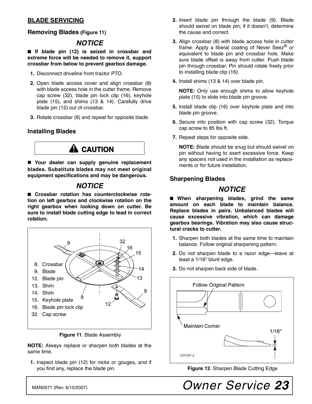
8.Crossbar
9.Blade
12.Blade pin
13.Shim
14.Shim
15.Keyhole plate
16.Blade pin lock clip
32.Cap screw
Figure 11. Blade Assembly
NOTE: Always replace or sharpen both blades at the same time.
1.Inspect blade pin (12) for nicks or gouges, and if you find any, replace the blade pin.
2.Insert blade pin through the blade (9). Blade should swivel on blade pin; if it doesn’t, determine the cause and correct.
3.Align crossbar (8) with blade access hole in cutter frame. Apply a liberal coating of Never Seez® or equivalent to blade pin and crossbar hole. Make sure blade offset is away from cutter. Push blade pin through crossbar. Pin should rotate freely prior to installing blade clip (16).
4.Install shims (13 & 14) over blade pin.
NOTE: Only use enough shims to allow keyhole plate (15) to slide into blade pin groove.
5.Install blade clip (16) over keyhole plate and into blade pin groove.
6.Secure into position with cap screw (32). Torque cap screw to 85 lbs ft.
7.Repeat steps for opposite side.
NOTE: Blade should be snug but should swivel on pin without having to exert excessive force. Keep any spacers not used in the installation as replace- ments or for future installation.
Sharpening Blades
NOTICE
■When sharpening blades, grind the same amount on each blade to maintain balance. Replace blades in pairs. Unbalanced blades will cause excessive vibration, which can damage gearbox bearings. Vibration may also cause struc- tural cracks to cutter.
1.Sharpen both blades at the same time to maintain balance. Follow original sharpening pattern.
2.Do not sharpen blade to a razor
3.Do not sharpen back side of blade.
Figure 12. Sharpen Blade Cutting Edge
MAN0571 (Rev. 6/15/2007) | Owner Service 23 |
|
|