Category 3 Standard Hitch
1.Position tractor lower lift arms between hitch mast plates.
2.Insert lower hitch pins to Position A, Figure 2, through mast plates and tractor lower lift arms.
3.Secure with lynch pins.
4.Attach top link for mounted units in the top hole of upper mast using top link pin.
Category 2 & 3 Quick Hitches
1.Position lower hitch pins to Position A, Figure 2.
2.Use the upper hole that matches upper quick hitch point location. This is usually the lower hole for Category 2 and the middle hole for Category 3.
3.Secure with lynch pins.
4.Attach tractor to cutter and secure hitch according to hitch manufacturer’s instructions.
NOTE: For DSO1260, place spacer sleeve (44) between tractor lower
DRIVELINE ADJUSTMENT
(MOUNTED & SEMI-MOUNTED)
Attach the cutter to the tractor
NOTICE
■If attaching cutter using a Quick Hitch the dis- tance between the tractor PTO and the gearbox input shaft will increase. Follow steps as you would for the
Raise and lower cutter and measure the maximum and minimum distance between the tractor PTO shaft and the gearbox input shaft. Separate the driveline into two halves and lay them
Set the two
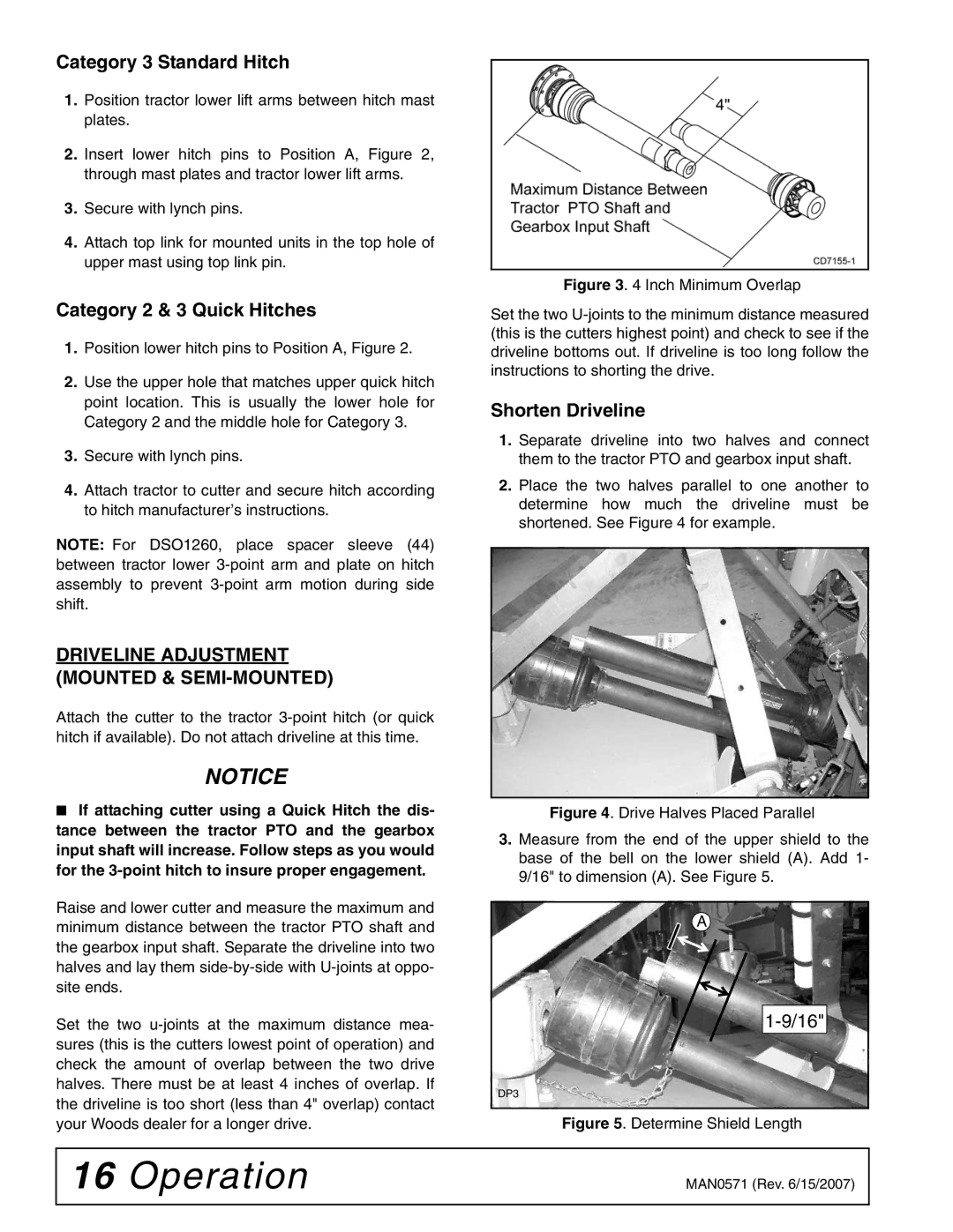
Figure 3. 4 Inch Minimum Overlap
Set the two U-joints to the minimum distance measured (this is the cutters highest point) and check to see if the driveline bottoms out. If driveline is too long follow the instructions to shorting the drive.
Shorten Driveline
1.Separate driveline into two halves and connect them to the tractor PTO and gearbox input shaft.
2.Place the two halves parallel to one another to determine how much the driveline must be shortened. See Figure 4 for example.
Figure 4. Drive Halves Placed Parallel
3.Measure from the end of the upper shield to the base of the bell on the lower shield (A). Add 1- 9/16" to dimension (A). See Figure 5.
A
DP3
Figure 5. Determine Shield Length
16 Operation | MAN0571 (Rev. 6/15/2007) |
|
|