7. | W1723: Lower the chip breaker onto the |
| board(s), using the chip breaker adjustment |
| setscrews shown in Figure 29. |
| W1724: Position the board to the far left |
| and lower the chip breaker onto the board, |
| then move the board to the far right and |
| lower the chip breaker onto the board. |
8. | Make sure that each of the adjustment |
| controls for the feed rollers and the chip |
| breaker are backed off enough so that they |
| will allow the components to move below |
| the current position on the board. |
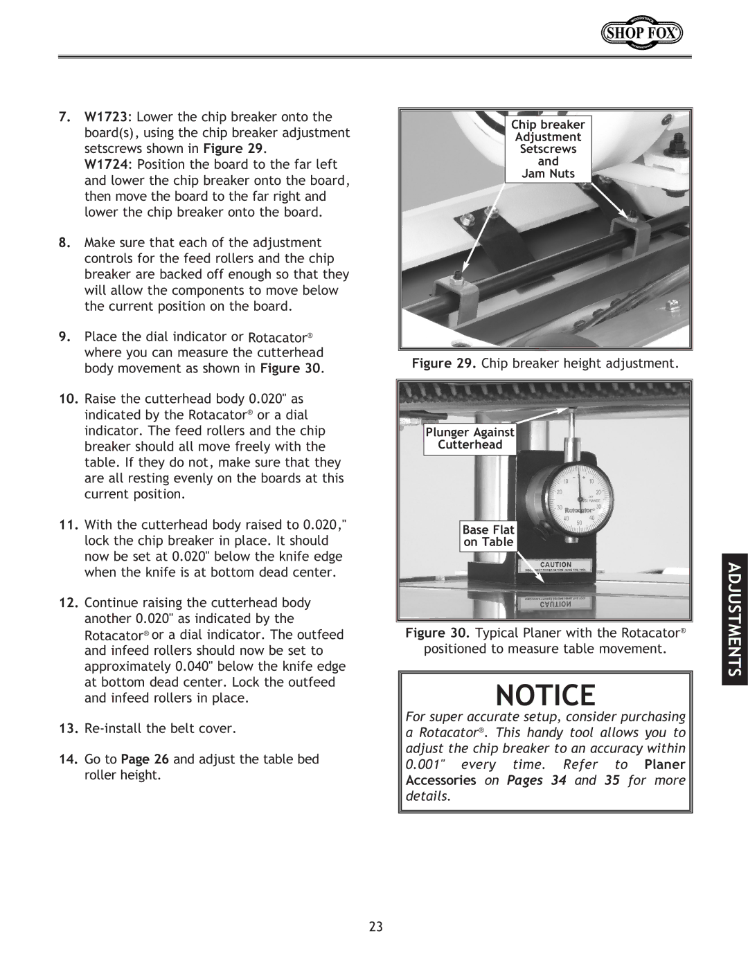
9. | Place the dial indicator or Rotacator® |
| where you can measure the cutterhead |
| body movement as shown in Figure 30. |
10. | Raise the cutterhead body 0.020" as |
| indicated by the Rotacator® or a dial |
| indicator. The feed rollers and the chip |
| breaker should all move freely with the |
| table. If they do not, make sure that they |
| are all resting evenly on the boards at this |
| current position. |
11. | With the cutterhead body raised to 0.020," |
| lock the chip breaker in place. It should |
| now be set at 0.020" below the knife edge |
| when the knife is at bottom dead center. |
12. | Continue raising the cutterhead body |
| another 0.020" as indicated by the |
| Rotacator® or a dial indicator. The outfeed |
Chip breaker
Adjustment
Setscrews
and
Jam Nuts
Figure 29. Chip breaker height adjustment.
Plunger Against
Cutterhead
Base Flat on Table
Figure 30. Typical Planer with the Rotacator®
ADJUSTMENTS
and infeed rollers should now be set to |
approximately 0.040" below the knife edge |
at bottom dead center. Lock the outfeed |
and infeed rollers in place. |
13. |
14. Go to Page 26 and adjust the table bed |
roller height. |
positioned to measure table movement.
NOTICE
For super accurate setup, consider purchasing a Rotacator®. This handy tool allows you to adjust the chip breaker to an accuracy within 0.001" every time. Refer to Planer Accessories on Pages 34 and 35 for more details.
23