ADJUSTMENTS
Chip Deflector
A chip deflector is mounted behind the cutterhead to keep wood chips from falling onto the outfeed roller.
To adjust the chip deflector, do these steps:
1.UNPLUG THE PLANER!
2.Remove the dust cover to access the chip breaker, and remove the belt cover.
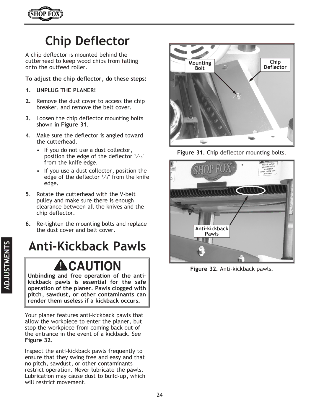
3.Loosen the chip deflector mounting bolts shown in Figure 31.
4. Make sure the deflector is angled toward the cutterhead.
•If you do not use a dust collector, position the edge of the deflector 1⁄16" from the knife edge.
•If you use a dust collector, position the edge of the deflector 1⁄4" from the knife edge.
5. Rotate the cutterhead with the
6.
Anti-Kickback Pawls
Unbinding and free operation of the anti- kickback pawls is essential for the safe operation of the planer. Pawls clogged with pitch, sawdust, or other contaminants can render them useless if a kickback occurs.
Your planer features
Inspect the
Mounting | Chip |
Bolt | Deflector |
Figure 31. Chip deflector mounting bolts.
Pawls
Figure 32. Anti-kickback pawls.
24