Inspecting Knives
(W1723)
The Model W1723 features a three straight- knife cutterhead. Correctly positioned knives act as a reference point for adjusting the feed rollers and the chip breaker. The knife edge should be within 0.002" from one end to the other. Improperly adjusted knives may unbalance the cutterhead, reduce the sharpness of knife edges prematurely, shorten bearing life, and produce poor planing results.
WEAR thick gloves and use extreme caution when working near planer knives. These knives are dangerously sharp! Failure to exercise care while working near knives could result in severe injury.
To check the knives, do these steps:
1.UNPLUG THE PLANER!
2.Remove the upper dust cover and dust port for access to the cutterhead.
3.Remove the plastic chip deflector.
4.Remove the
5.Using the
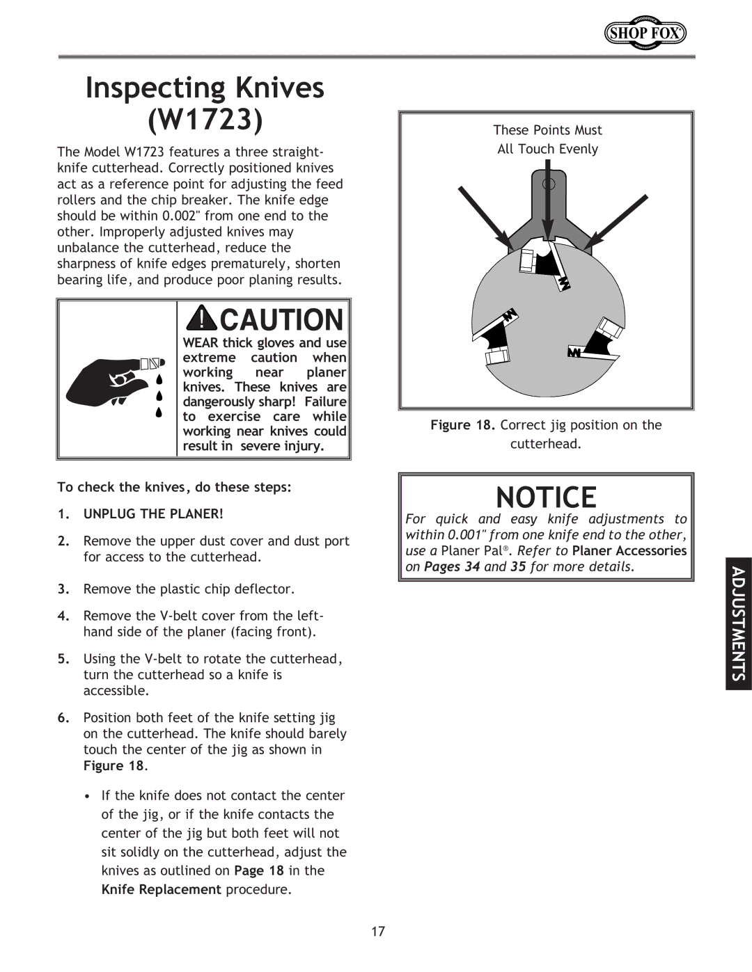
6.Position both feet of the knife setting jig on the cutterhead. The knife should barely touch the center of the jig as shown in
Figure 18.
•If the knife does not contact the center of the jig, or if the knife contacts the center of the jig but both feet will not sit solidly on the cutterhead, adjust the knives as outlined on Page 18 in the
Knife Replacement procedure.
These Points Must
All Touch Evenly
Figure 18. Correct jig position on the
cutterhead.
NOTICE |
|
For quick and easy knife adjustments to |
|
within 0.001" from one knife end to the other, |
|
use a Planer Pal®. Refer to Planer Accessories |
|
on Pages 34 and 35 for more details. | ADJUSTMENTS |
|
17