Installation
Knockout Preparation
Knockout preparation should be done before mounting either the inverter or the Long AC Conduit Box.
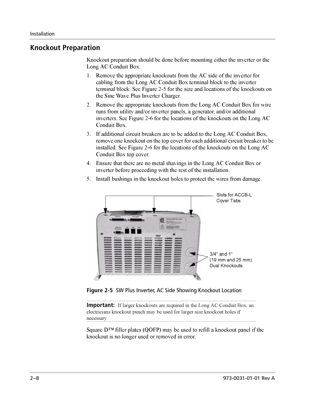
1.Remove the appropriate knockouts from the AC side of the inverter for cabling from the Long AC Conduit Box terminal block to the inverter terminal block. See Figure
2.Remove the appropriate knockouts from the Long AC Conduit Box for wire runs from utility and/or inverter panels, a generator, and/or additional inverters. See Figure
3.If additional circuit breakers are to be added to the Long AC Conduit Box, remove one knockout on the top cover for each additional circuit breaker to be installed. See Figure
4.Ensure that there are no metal shavings in the Long AC Conduit Box or inverter before proceeding with the rest of the installation.
5.Install bushings in the knockout holes to protect the wires from damage.
Slots for
Cover Tabs
![]() 3/4" and 1"
3/4" and 1"
(19 mm and 25 mm) Dual Knockouts
Figure 2-5 SW Plus Inverter, AC Side Showing Knockout Location
Important: If larger knockouts are required in the Long AC Conduit Box, an electricians knockout punch may be used for larger size knockout holes if necessary.
Square D™ filler plates (QOFP) may be used to refill a knockout panel if the knockout is no longer used or removed in error.