Additional Accessory Wiring
Additional Accessory Wiring
If you have any of the following accessories connected (or to be connected) to your inverter, then you will also need to pass their connecting cables through the Long AC Conduit Box to the AC side of the inverter:
•Generator Start Module (GSM) for automatic generator control
•Auxiliary Load Module (ALM) for controlling auxiliary loads such as alarms or ventilator fans
•Emergency Power Off (EPO) switch (not supplied by Xantrex)
•Inverter Control Module (ICM), or an Inverter Communications Adapter (ICA) for remote control and monitoring of the inverter
•Inverter Stacking Control – Series
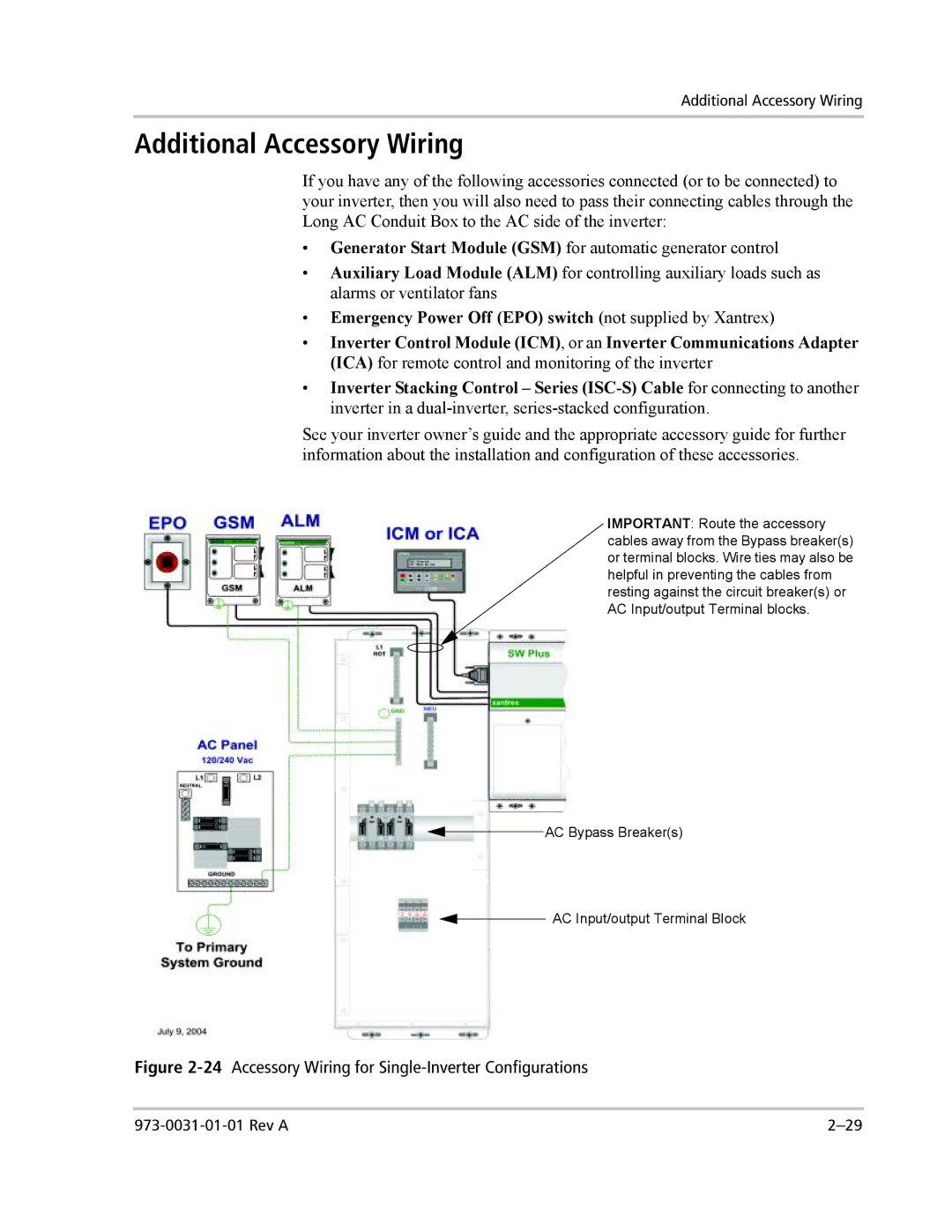
See your inverter owner’s guide and the appropriate accessory guide for further information about the installation and configuration of these accessories.
IMPORTANT: Route the accessory cables away from the Bypass breaker(s) or terminal blocks. Wire ties may also be helpful in preventing the cables from resting against the circuit breaker(s) or AC Input/output Terminal blocks.
![]() AC Bypass Breaker(s)
AC Bypass Breaker(s)
![]() AC Input/output Terminal Block
AC Input/output Terminal Block