Installation and Configuration
Remote/Local Operation
Remote/Local Operation
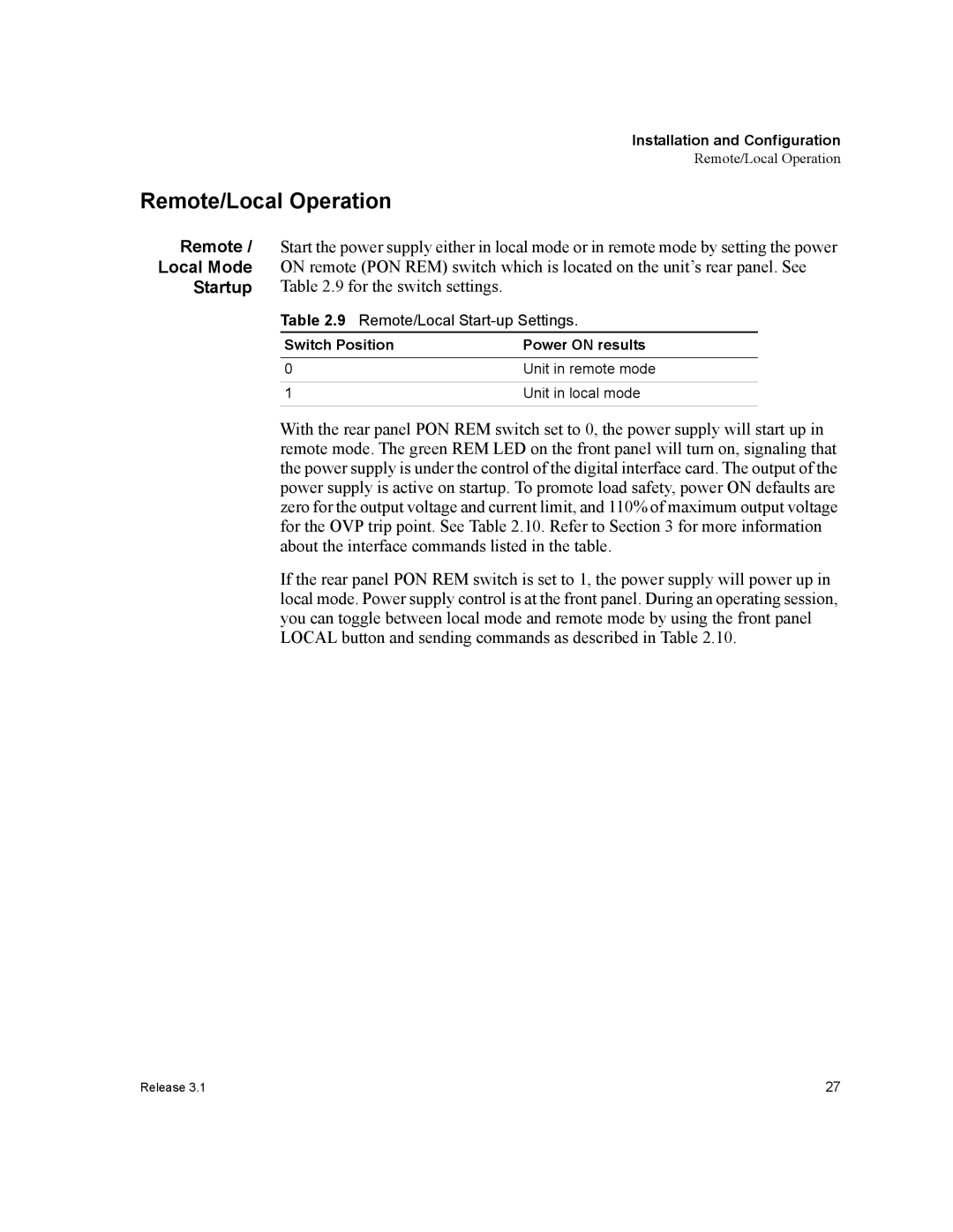
Remote / | Start the power supply either in local mode or in remote mode by setting the power | ||
Local Mode | ON remote (PON REM) switch which is located on the unit’s rear panel. See | ||
Startup | Table 2.9 for the switch settings. |
|
|
| Table 2.9 Remote/Local |
| |
| Switch Position | Power ON results | |
|
|
|
|
| 0 | Unit in remote mode | |
|
|
|
|
| 1 | Unit in local mode | |
|
|
|
|
With the rear panel PON REM switch set to 0, the power supply will start up in remote mode. The green REM LED on the front panel will turn on, signaling that the power supply is under the control of the digital interface card. The output of the power supply is active on startup. To promote load safety, power ON defaults are zero for the output voltage and current limit, and 110% of maximum output voltage for the OVP trip point. See Table 2.10. Refer to Section 3 for more information about the interface commands listed in the table.
If the rear panel PON REM switch is set to 1, the power supply will power up in local mode. Power supply control is at the front panel. During an operating session, you can toggle between local mode and remote mode by using the front panel LOCAL button and sending commands as described in Table 2.10.
Release 3.1 | 27 |
