Installation and Configuration
Basic Setup Procedure
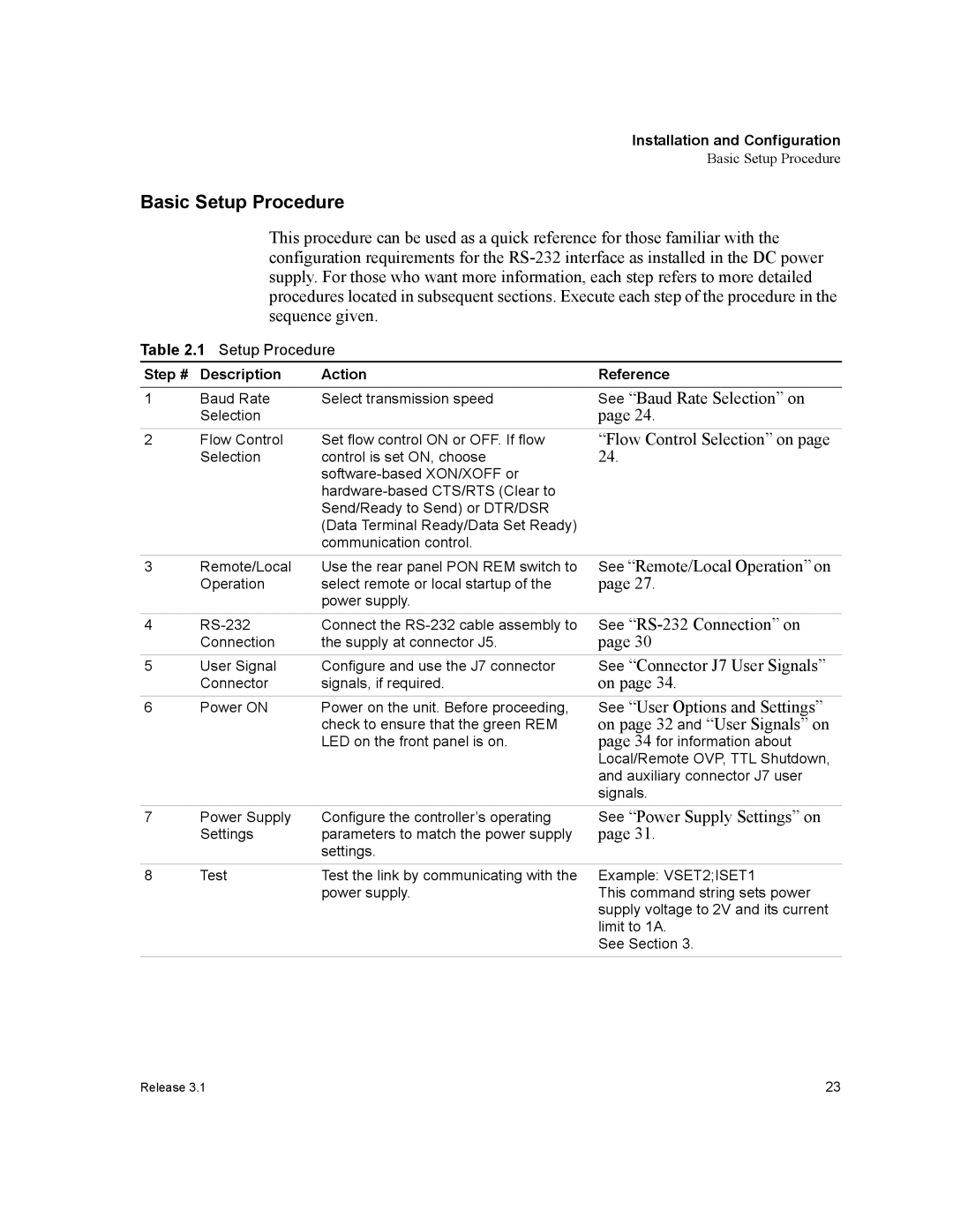
Basic Setup Procedure
This procedure can be used as a quick reference for those familiar with the configuration requirements for the
Table 2.1 Setup Procedure
Step # | Description | Action | Reference |
1 | Baud Rate | Select transmission speed | See “Baud Rate Selection” on |
| Selection |
| page 24. |
2 | Flow Control | Set flow control ON or OFF. If flow |
| Selection | control is set ON, choose |
|
|
“Flow Control Selection” on page 24.
3 | Remote/Local | Use the rear panel PON REM switch to | See “Remote/Local Operation” on |
| Operation | select remote or local startup of the | page 27. |
|
| power supply. |
|
4 | Connect the | See | |
| Connection | the supply at connector J5. | page 30 |
5 | User Signal | Configure and use the J7 connector | See “Connector J7 User Signals” |
| Connector | signals, if required. | on page 34. |
6 | Power ON | Power on the unit. Before proceeding, |
|
| check to ensure that the green REM |
|
| LED on the front panel is on. |
See “User Options and Settings” on page 32 and “User Signals” on page 34 for information about Local/Remote OVP, TTL Shutdown, and auxiliary connector J7 user signals.
7 | Power Supply | Configure the controller’s operating |
| Settings | parameters to match the power supply |
|
| settings. |
See “Power Supply Settings” on page 31.
8 | Test | Test the link by communicating with the | Example: VSET2;ISET1 |
|
| power supply. | This command string sets power |
|
|
| supply voltage to 2V and its current |
limit to 1A. See Section 3.
Release 3.1 | 23 |