HTY-750
QUICK REFERENCE GUIDE
Items used for connections and operations
in this guide
s Audio pin cable (x1)
s OSD* video pin cable (x1) s Optical cable (x1)
s Digital audio pin cable (x1) s IntelliBeam microphone (x1)
s Cardboard microphone stand (x1) s Demonstration DVD (x1)
*OSD:
2 | Connecting external components to this unit |
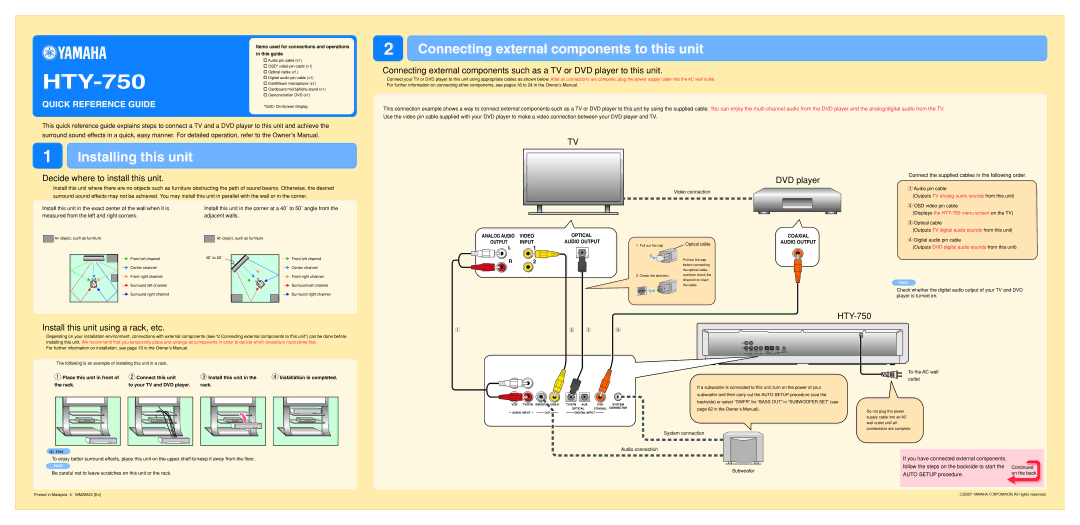
Connecting external components such as a TV or DVD player to this unit.
Connect your TV or DVD player to this unit using appropriate cables as shown below. After all connections are complete, plug the power supply cable into the AC wall outlet.
For further information on connecting other components, see pages 16 to 24 in the Owner’s Manual.
This connection example shows a way to connect external components such as a TV or DVD player to this unit by using the supplied cable. You can enjoy the
This quick reference guide explains steps to connect a TV and a DVD player to this unit and achieve the surround sound effects in a quick, easy manner. For detailed operation, refer to the Owner’s Manual.
1 | Installing this unit |
TV
Decide where to install this unit.
Install this unit where there are no objects such as furniture obstructing the path of sound beams. Otherwise, the desired surround sound effects may not be achieved. You may install this unit in parallel with the wall or in the corner.
Install this unit in the exact center of the wall when it is | Install this unit in the corner at a 40˚ to 50˚ angle from the | |
measured from the left and right corners. | adjacent walls. |
|
An object, such as furniture | An object, such as furniture |
|
Front left channel | 40˚ to 50˚ | Front left channel |
| ||
Center channel |
| Center channel |
Front right channel |
| Front right channel |
Surround left channel |
| Surround left channel |
Surround right channel |
| Surround right channel |
Install this unit using a rack, etc.
Depending on your installation environment, connections with external components (see “2 Connecting external components to this unit”) can be done before installing this unit. We recommend that you temporarily place and arrange all components in order to decide which procedure must come first.
For further information on installation, see page 13 in the Owner’s Manual.
The following is an example of installing this unit in a rack.
ANALOG AUDIO VIDEO
OUTPUT INPUT
L1
R2
1
OPTICAL
AUDIO OUTPUT
1. Pull out the cap
2. Check the direction
2 | 3 | 4 |
Video connection
Optical cable
Pull out the cap before connecting the optical cable, and then check the direction to insert the cable.
DVD player
COAXIAL
AUDIO OUTPUT
HTY-750
L
R
VCR TV/STB | SUBWOOFER VIDEO | TV/STB AUX |
| DVD | SYSTEM | |||||
|
|
|
|
|
| OPTICAL | COAXIAL CONNECTOR | |||
AUDIO INPUT |
|
| OUT |
|
|
| DIGITAL INPUT |
|
| |
Connect the supplied cables in the following order.
1Audio pin cable
(Outputs TV analog audio sounds from this unit)
2OSD video pin cable
(Displays the
3Optical cable
(Outputs TV digital audio sounds from this unit)
4Digital audio pin cable
(Outputs DVD digital audio sounds from this unit)
Note
Check whether the digital audio output of your TV and DVD player is turned on.
1 Place this unit in front of | 2 Connect this unit | ||||||
the rack. | to your TV and DVD player. | ||||||
|
|
|
|
|
|
|
|
|
|
|
|
|
|
|
|
|
|
|
|
|
|
|
|
|
|
|
|
|
|
|
|
3Install this unit in the 4 Installation is completed.
L
VCR TV/STB SUBWOOFER VIDEO
AUDIO INPUT |
|
|
| OUT |
|
|
TV/STB AUX |
| DVD | SYSTEM | ||
OPTICAL | COAXIAL | CONNECTOR | |||
| DIGITAL INPUT |
|
|
| |
|
|
| |||
If a subwoofer is connected to this unit, turn on the power of your subwoofer and then carry out the AUTO SETUP procedure (see the backside) or select “SWFR” for “BASS OUT” in “SUBWOOFER SET” (see page 62 in the Owner’s Manual).
To the AC wall outlet
Do not plug the power supply cable into an AC wall outlet until all connections are complete.
yHint
System connection
Audio connection
To enjoy better surround effects, place this unit on the upper shelf to keep it away from the floor.
Note
Be careful not to leave scratches on this unit or the rack.
|
|
| If you have connected external components, |
|
|
|
| follow the steps on the backside to start the | Continued |
Subwoofer | on the back | |||
|
|
| AUTO SETUP procedure. | |
Printed in Malaysia | WM28920 [En] | C2007 |
| All rights reserved. |
| ||||
|