036-21410-001-A-0502
ECONOMIZER / MOTORIZED DAMPER FIXED OUTDOOR INTAKE AIR AND POWER EXHAUST RAIN HOODS (See detail Y)
BLOWER | BLOWER MOTOR | BLOWER | |
COMPARTMENT | ACCESS | ||
ACCESS | |||
ACCESS |
| ||
|
| ||
(Auxillary) |
|
| |
DOT PLUG |
| ||
|
| ||
(For pressure |
|
| |
drop reading) |
|
| |
GAS OR |
|
| |
ELECTRIC |
|
| |
HEAT ACCESS |
| ||
VENT AIR |
|
| |
OUTLET |
|
| |
HOODS |
|
| |
COMBUSTION
AIR INLET HOOD
(C) GAS
SUPPLY
ENTRY ![]()
21.00
5
COMPRESSOR ACCESS | |
| (See detail X) |
COIL
GUARD
KIT
CONDENSER
COILS
(A)CONTROL WIRING
92ENTRY
DISCONNECT
CONTROL BOX | |
ACCESS | |
| |
35 |
|
| |
| RETURN |
33 | AIR |
SWITCH
LOCATION
(B) POWER | All dimensions are in inches. They are | |
WIRING ENTRY | ||
subject to change without notice. | ||
| ||
BOTTOM SUPPLY | Certified dimensions will be provided | |
upon request. | ||
AND RETURN | ||
| ||
AIR OPENINGS |
|
(See Note)
UNIT BASE RAILS
Shown separately to illustrate | (D) |
Bottom Duct openings. Power | GAS SUPPLY |
and Gas Piping Connection | ENTRY |
location. |
NOTE: |
| |
For curb mounted units, refer to the curb hanger |
| |
| ||
dimensions of the curb for proper size of the |
| |
supply and return air duct connections. |
|
|
|
|
|
SUPPLY | |
AIR |
| (B) POWER WIRING |
| ENTRY |
(A) CONTROL WIRING | |
| ENTRY |
| |
|
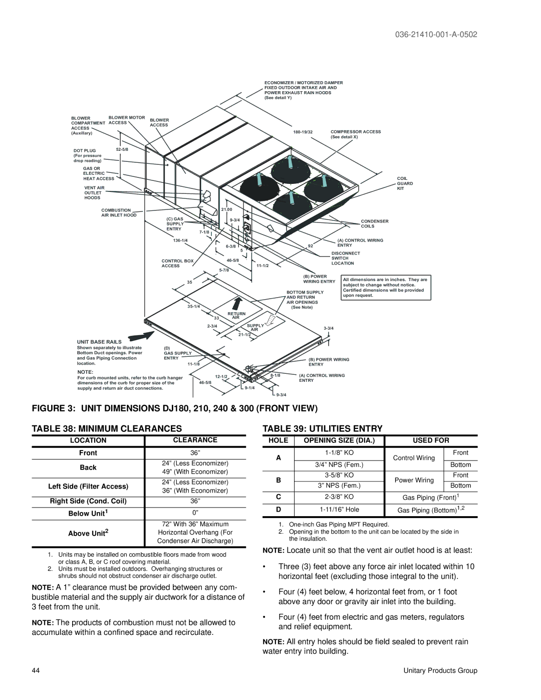
FIGURE 3: UNIT DIMENSIONS DJ180, 210, 240 & 300 (FRONT VIEW)
TABLE 38: MINIMUM CLEARANCES
LOCATION | CLEARANCE | |
|
| |
Front | 36” | |
|
| |
Back | 24” (Less Economizer) | |
49” (With Economizer) | ||
| ||
|
| |
Left Side (Filter Access) | 24” (Less Economizer) | |
36” (With Economizer) | ||
| ||
|
| |
Right Side (Cond. Coil) | 36” | |
|
| |
Below Unit1 | 0” | |
Above Unit2 | 72” With 36” Maximum | |
Horizontal Overhang (For | ||
| Condenser Air Discharge) | |
|
|
1.Units may be installed on combustible floors made from wood or class A, B, or C roof covering material.
2.Units must be installed outdoors. Overhanging structures or shrubs should not obstruct condenser air discharge outlet.
NOTE: A 1” clearance must be provided between any com- bustible material and the supply air ductwork for a distance of 3 feet from the unit.
NOTE: The products of combustion must not be allowed to accumulate within a confined space and recirculate.
TABLE 39: UTILITIES ENTRY
HOLE | OPENING SIZE (DIA.) | USED FOR | ||
|
|
|
| |
A | Control Wiring | Front | ||
|
| |||
| 3/4” NPS (Fem.) |
| Bottom | |
|
|
|
| |
B | Power Wiring | Front | ||
|
| |||
3” NPS (Fem.) | Bottom | |||
|
| |||
|
|
|
| |
C | Gas Piping (Front)1 | |||
D | Gas Piping (Bottom)1,2 | |||
1.
2.Opening in the bottom to the unit can be located by the side in the insulation.
NOTE: Locate unit so that the vent air outlet hood is at least:
•Three (3) feet above any force air inlet located within 10 horizontal feet (excluding those integral to the unit).
•Four (4) feet below, 4 horizontal feet from, or 1 foot above any door or gravity air inlet into the building.
•Four (4) feet from electric and gas meters, regulators and relief equipment.
NOTE: All entry holes should be field sealed to prevent rain water entry into building.
44 | Unitary Products Group |