FITTING THE CONTROL UNIT
Check that the control unit voltage, which is shown on the label on the side of the control unit case, is correct for the available
The control unit model number has a suffix, which relates to the supply voltage.
US is 120 volts
EU is 220 volts
UK is 240 volts
The US/120 volt control unit will operate on a 60 cycle
The control unit is mounted in a convenient position near and within sight of the door and at least 1.5 metres or 5 feet from the ground, with screws provided passed through the mounting holes in the corner pillars, which are outside of the waterproof gasket. (Pic 17)
Pic 17
Do not drill holes in the back of the case, as this is liable to allow water ingress and cause damage to the back of the printed circuit board.
Site the control unit so that any conduits are routed to the BOTTOM of the case. DO NOT drill the top or sides of the case as condensation within the conduit will run down onto the panel and cause operating problems and probable damage.
If the printed circuit board has to be removed from its case, ensure that it is handled with care and not placed on its back on any hard surfaces as this may damage the ceramic surface mount components on the rear of the printed circuit board.
The control unit lid can be temporarily secured to the case side screw positions to prevent it hanging by the cables during the setting up process.
(Pic 18)
Pic 18
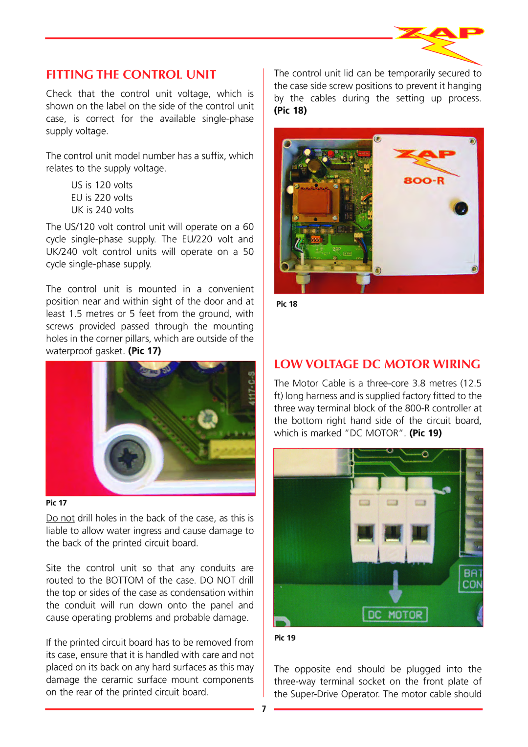
LOW VOLTAGE DC MOTOR WIRING
The Motor Cable is a
Pic 19
The opposite end should be plugged into the
7