If the safety circuit is interrupted whist the door is closing then the door will stop and reopen.
If the safety circuit is interrupted whist the door is operating with the
INTERLOCK CIRCUIT WIRING
A pair of terminals is provided to enable a pass door switch or a key switch to be interlocked to the control unit, to prevent the door opening if the interlock terminals are open circuit. (Pic 45).
Pic 45
An
A Slide Lock switch may be fitted and wired to the interlock terminals. However this is not essential as the Control unit will detect the obstruction and stop the door if the slide lock is left in the locked position.
ACCESSORY RADIO RECEIVER WIRING
A
Pic 46
The Radio transmitter button will operate as: Press to open – Press to stop – Press to close – Press to stop.
The wiring of a
A Zap radio receiver model 840 may be fitted in the socket marked “ZAP RADIO” at the top left- hand side of the panel. (Pic 47)
Pic 47
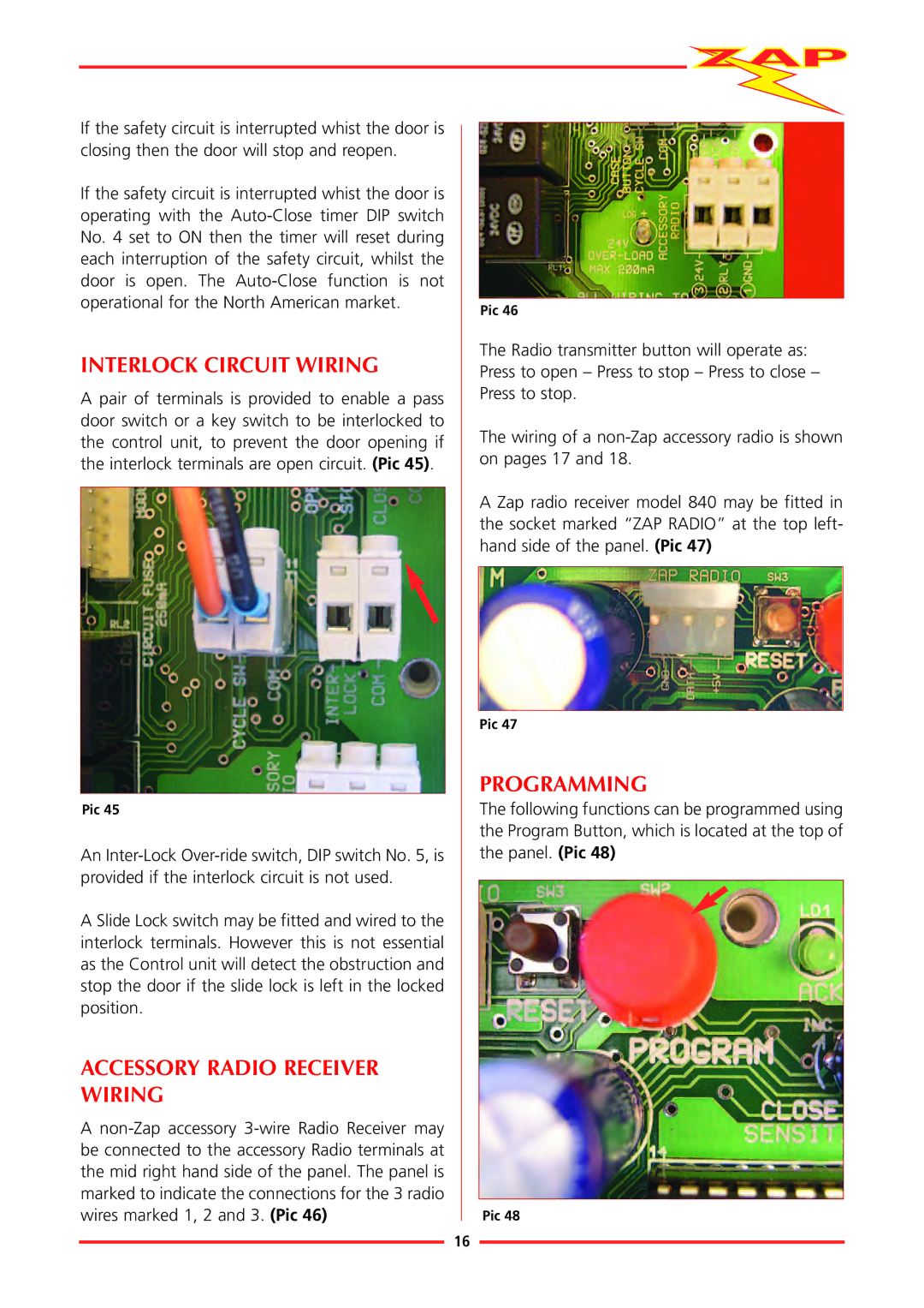
PROGRAMMING
The following functions can be programmed using the Program Button, which is located at the top of the panel. (Pic 48)
Pic 48
16