The second Allen screw, set at 90 degrees, should then be tightened and secured with the locknut. Now tighten the torque arm screws (Pic 10)
Pic 10
FITTING THE MANUAL OVER-RIDE LEVER MECHANISM
The position of the cable post should be assessed next. The Cable Post, which secures the Bowden cable outer sheath, is fixed to the door track or frame using two M6 flat head screws and flange nuts supplied. Drill two M6 or 1/4 inch holes in the door track or frame in a position at least 25mm or one inch higher than the fully extended position of the outer cable, to allow movement of the upper section of the outer sheath. (Pic 11)
Pic 11
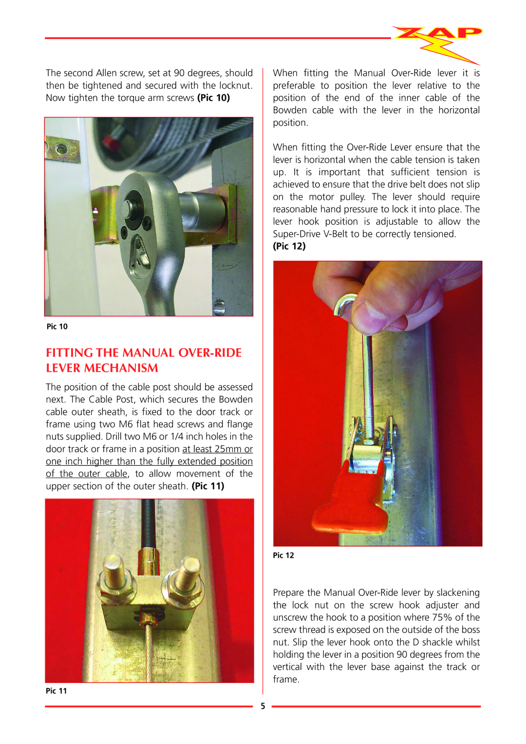
When fitting the Manual Over-Ride lever it is preferable to position the lever relative to the position of the end of the inner cable of the Bowden cable with the lever in the horizontal position.
When fitting the Over-Ride Lever ensure that the lever is horizontal when the cable tension is taken up. It is important that sufficient tension is achieved to ensure that the drive belt does not slip on the motor pulley. The lever should require reasonable hand pressure to lock it into place. The lever hook position is adjustable to allow the Super-Drive V-Belt to be correctly tensioned.
(Pic 12)
Pic 12
Prepare the Manual Over-Ride lever by slackening the lock nut on the screw hook adjuster and unscrew the hook to a position where 75% of the screw thread is exposed on the outside of the boss nut. Slip the lever hook onto the D shackle whilst holding the lever in a position 90 degrees from the vertical with the lever base against the track or frame.