Zap 815-RL installation instructions

Models: 815-RL

1 28
Download 28 pages 63.62 Kb
Page 9
Image 9
Next slide the Super-Drive assembly onto the door shaft and select a suitable hole in the torque arm to bolt it to the Super-Drive back plate using the spacer bush, which should pass through the lower slot in the Cover back. (Pic 7) The Cover back will be secured later. The Torque Arm should be approximately at right angles to the Super-Drive assembly.

Pic 6

Next slide the Super-Drive assembly onto the door shaft and select a suitable hole in the torque arm to bolt it to the Super-Drive back plate using the spacer bush, which should pass through the lower slot in the Cover back. (Pic 7) The Cover back will be secured later. The Torque Arm should be approximately at right angles to the Super-Drive assembly.

Pic 7

Align the Super-Drive keyway with the door shaft keyway and fit the key supplied with the package. Ensure that the two Allen screws are firmly tight and then tighten the lock nuts. (Pic 8)

Pic 8

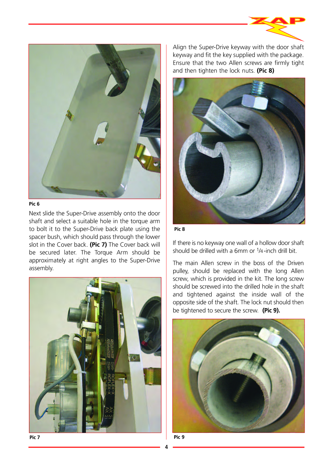
If there is no keyway one wall of a hollow door shaft should be drilled with a 6mm or 1/4 -inch drill bit.

The main Allen screw in the boss of the Driven pulley, should be replaced with the long Allen screw, which is provided in the kit. The long screw should be screwed into the drilled hole in the shaft and tightened against the inside wall of the opposite side of the shaft. The lock nut should then be tightened to secure the screw. (Pic 9).

Pic 9

4

Page 9
Image 9
Zap 815-RL installation instructions