16
Installation
Top of Form (TOF) Sensor
Top of Form (TOF) Sensor
The TTP 2100 has a flexible top of form detection system. When delivered the printer is configured with fork (transmissive) sensor to detect holes/gaps between tickets. The holes/gaps should be in the paper center, 12.5 mm to the right of the center (according to IATA resolution 740) or at the edge of 82.5 mm wide tickets (Boarding cards).
If the TOF mark is at a suitable position, an auto calibration routine will configure everything for you.
You can move the sensor to other positions, force the printer to use a specific sensor, switch to reflex (black mark) sensor for
Selecting Fork (Transmissive) or Reflex (Black Mark) TOF Sensor
The TTP 2100 can use a fork (transmissive) sensor that looks for holes between tickets, or a reflex (black mark) sensor that looks for
Positioning the TOF Sensor
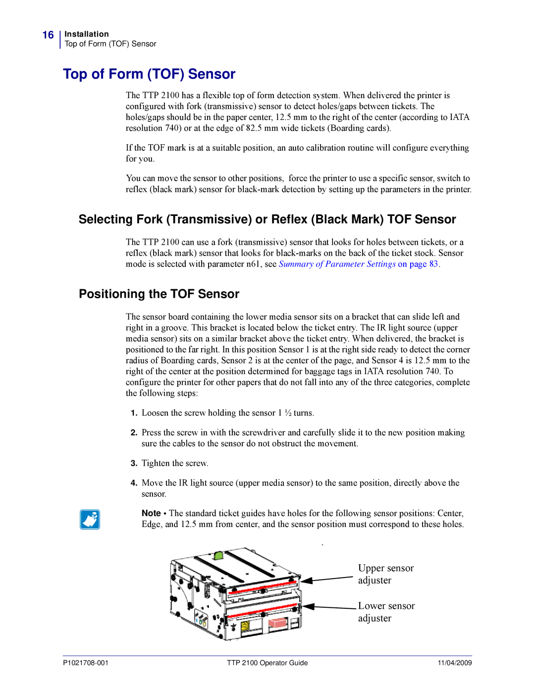
The sensor board containing the lower media sensor sits on a bracket that can slide left and right in a groove. This bracket is located below the ticket entry. The IR light source (upper media sensor) sits on a similar bracket above the ticket entry. When delivered, the bracket is positioned to the far right. In this position Sensor 1 is at the right side ready to detect the corner radius of Boarding cards, Sensor 2 is at the center of the page, and Sensor 4 is 12.5 mm to the right of the center at the position determined for baggage tags in IATA resolution 740. To configure the printer for other papers that do not fall into any of the three categories, complete the following steps:
1.Loosen the screw holding the sensor 1 ½ turns.
2.Press the screw in with the screwdriver and carefully slide it to the new position making sure the cables to the sensor do not obstruct the movement.
3.Tighten the screw.
4.Move the IR light source (upper media sensor) to the same position, directly above the sensor.
Note • The standard ticket guides have holes for the following sensor positions: Center, Edge, and 12.5 mm from center, and the sensor position must correspond to these holes.
a3
Upper sensor adjuster
![]() Lower sensor adjuster
Lower sensor adjuster
TTP 2100 Operator Guide | 11/04/2009 |