24
Installation
Connecting to the Computer
Connecting to the Computer
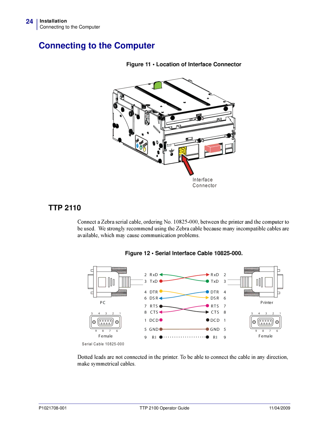
Figure 11 • Location of Interface Connector
In te rfa ce
C o n n e cto r
TTP 2110
Connect a Zebra serial cable, ordering No.
Figure 12 • Serial Interface Cable 10825-000.
P C |
5 4 3 2 1
9 8 7 6
F emale
S e ria l C a b le 1 0 8 2 5
2 | R xD | R xD | 2 |
|
|
|
|
3 | T xD | T xD | 3 |
|
|
|
|
4 | DT R | DT R | 4 |
|
|
|
|
6 | DS R | DS R | 6 |
| P rinter |
| |
7 | R T S | R T S | 7 |
|
| ||
|
|
|
| ||||
8 | C T S | C T S | 8 | 5 | 4 | 3 2 | 1 |
1 | DC D | DC D | 1 |
|
|
|
|
5 | G ND | G ND | 5 | 9 | 8 | 7 | 6 |
9 | R I | R I | 9 |
| F emale |
| |
|
|
|
| ||||
Dotted leads are not connected in the printer. To be able to connect the cable in any direction, make symmetrical cables.
TTP 2100 Operator Guide | 11/04/2009 |
