Polaris P1000i, P2000i manual Parallel Generator Operation, Parallel operation procedure

Page 39

OPERATION

Parallel Generator Operation

Parallel operation features, kits sold separately.

Two POLARIS parallel ready generators can be connected together to increase the total power available to a load. The system seamlessly matches frequency and automatically evenly distributes the load to each generator so one is not overloaded.

Operating the generators in parallel has 0.9 power de-rate factor. For example, connecting a 1kw and 2kw together in parallel operation, the continuous rated combined output will equal 0.9x (900w + 1600w) = 2250W.

Any combination of two POLARIS parallel ready generators can be connected such as a P2000i and a P1000i, two P2000i models, etc. There are two different parallel connection kits. One kit has a 30A receptacle ideal for connecting two P2000i models or a P2000i and a P1000i.

Parallel operation procedure

1.Turn off both generators and disconnect all the electrical devices from the generators

2.Prepare two parallel ready generators for operation. Place them on a hard and level surface.
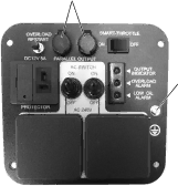
3.

Connect the parallel kit to each

A


generator by inserting one pair of


leads from the parallel box to the


parallel receptacles (A) on the


panel


4.

Ground the generators (B).

B

5.Start both generators and confirm that both green "RUN" lights are illuminated. The Smart throttle system may be used as long as the Smart throttle setting of both generators is the same.

6.Securely plug the electrical appliance plug into parallel cable receptacle and switch on the electrical appliance power supply.

38

Image 39
Contents Polaris Power Table of Contents Welcome IntroductionIntended Use Safety Precautions Alcohol or Drug USE Signal Words and Safety TermsP1000iP2000i Identification Numbers and LocationsBefore and During Operation SafetySafety Warnings and Precautions GeneralFire Safety Operator Safety Fuel Safety Carbon Monoxide Safety Electrical Safety Equipment Modifications Extension Cord InformationHot Exhaust Caution Safety Labels and LocationsCarbon Monoxide Warning Outdoor Use only Danger LabelSafety Generator Components Controls and FeaturesP1000i P2000i Control Panel ComponentsStarter Recoil Grip Engine Fuel SwitchChoke Lever Fuel Tank Cap Vent LeverDC Receptacle and Fuse Smart Throttle SwitchIndicator Panel Ground TerminalAC Receptacles Parallel Receptacles Overload Protector Reset SwitchAdding Engine Oil First USE InstructionsFuel Recommendation Adding Fuel PRE-OPERATION Inspection Pre-Operation ChecklistRefueling Safe Operating PrecautionsOperation Fuel RecommendationsRemove the fuel tank cap a Starting the Engine Before Starting the EnginePosition the engine switch to on Stopping the Engine AC Operation AC Capacity Wattage Reference Table DC Operation Power ManagementOperation Smart Throttle System Disconnecting the Battery Charging CableConnections to a Building Electrical System Standby PowerParallel Generator Operation Parallel operation procedureShutting off the generators Carburetor Modification High Altitude UseEmission Control System Information Source of EmissionsAlterations Replacement Parts Problems Affecting EmissionsImportance of Maintenance MaintenanceSafety Precautions Maintenance SafetyPeriodic Maintenance Chart Periodic MaintenanceOpening the Service Door Fuel Line Inspection Initial MaintenanceFuel System Hour Initial Break-InOFF Engine Oil Oil RecommendationOil Level Inspection Oil Change Procedure Maintenance Air Filter Inspection Air FiltersAir Filter Replacement Air Filter CleaningSpark Plug Spark Plug Inspection and ReplacementGap should be 0.6 0.7 mm Transportation and Storage TransportationTransporting the Generator Storage Preparation StorageAccessing the Fuel Tank Draining Fuel from the Fuel Tank and Carburetor Fogging the Engine Removing from Storage Storage PrecautionsGeneral Specifications SpecificationsModified coefficient table of ambient condition power Polaris Lubricants and Maintenance ProductsP1000i Wiring Diagram Wiring DiagramsRed Gray Brown White Black P2000i Wiring DiagramEngine Turns Over, but Will Not Start TroubleshootingTroubleshooting Symptoms Engine Will Not Turn OverEngine Backfires Engine Lacks PowerEngine Runs Irregularly, Stalls, or Misfires Engine Pings or KnocksPossible Lean Solution Fuel Cause No Power at DC ReceptacleEngine Stops or Loses Power No Power at AC ReceptaclesAbout this Warranty Document Warranty Registration Form WarrantyWarranty Period Warranty Exclusions Polaris Power Generator Owner Responsibility Important Notice DATE/HOURS Service Comments Supplier Permormed Technician Maintenance LOGLabel Location IndexIndex PMS