


TRANSFORMER WIRING
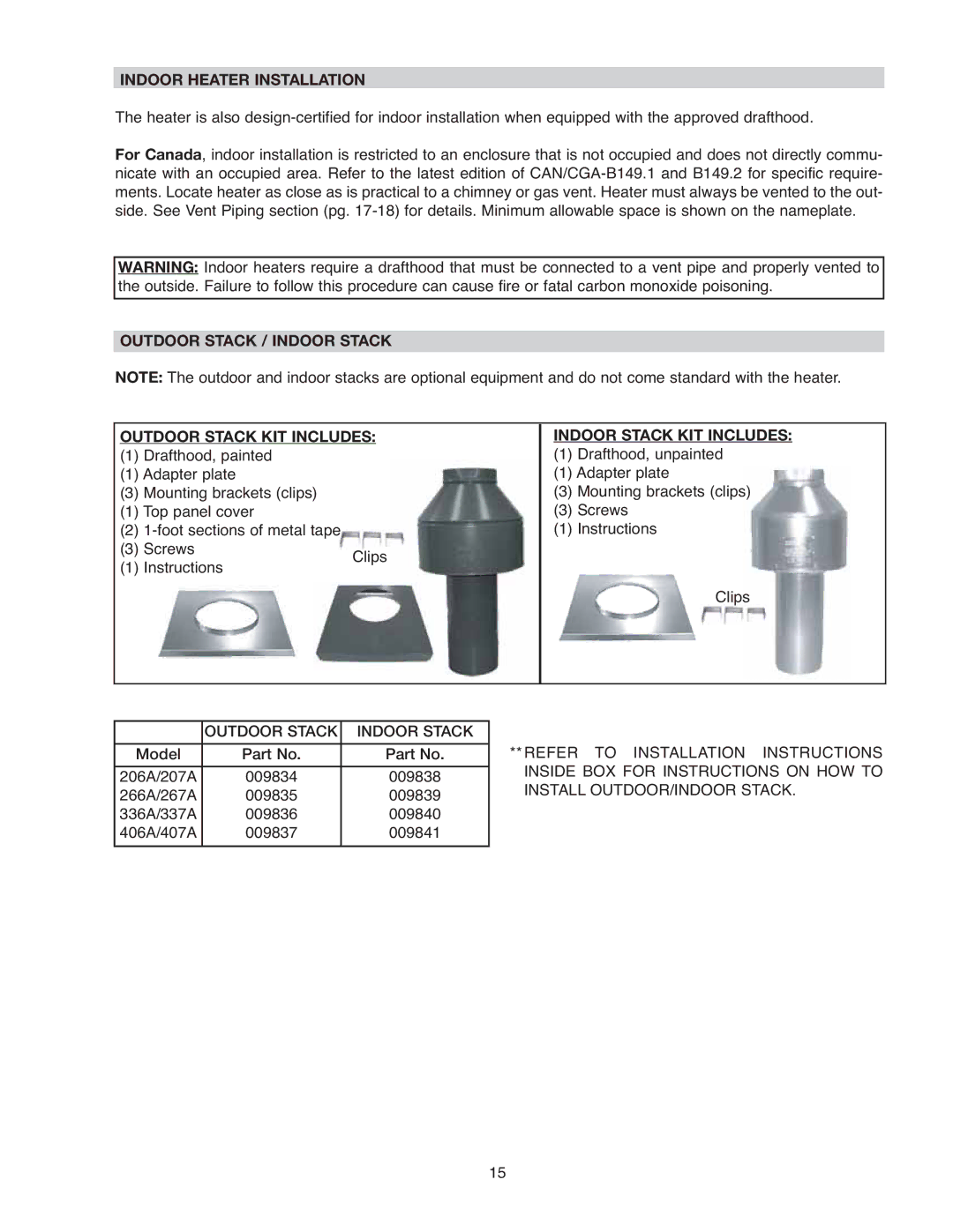
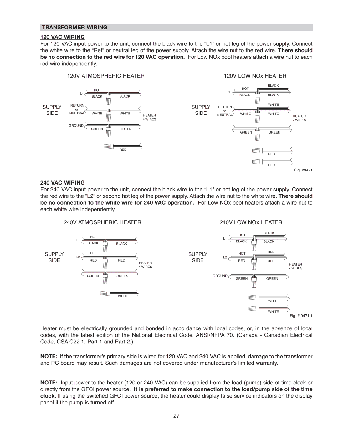
120 VAC WIRING
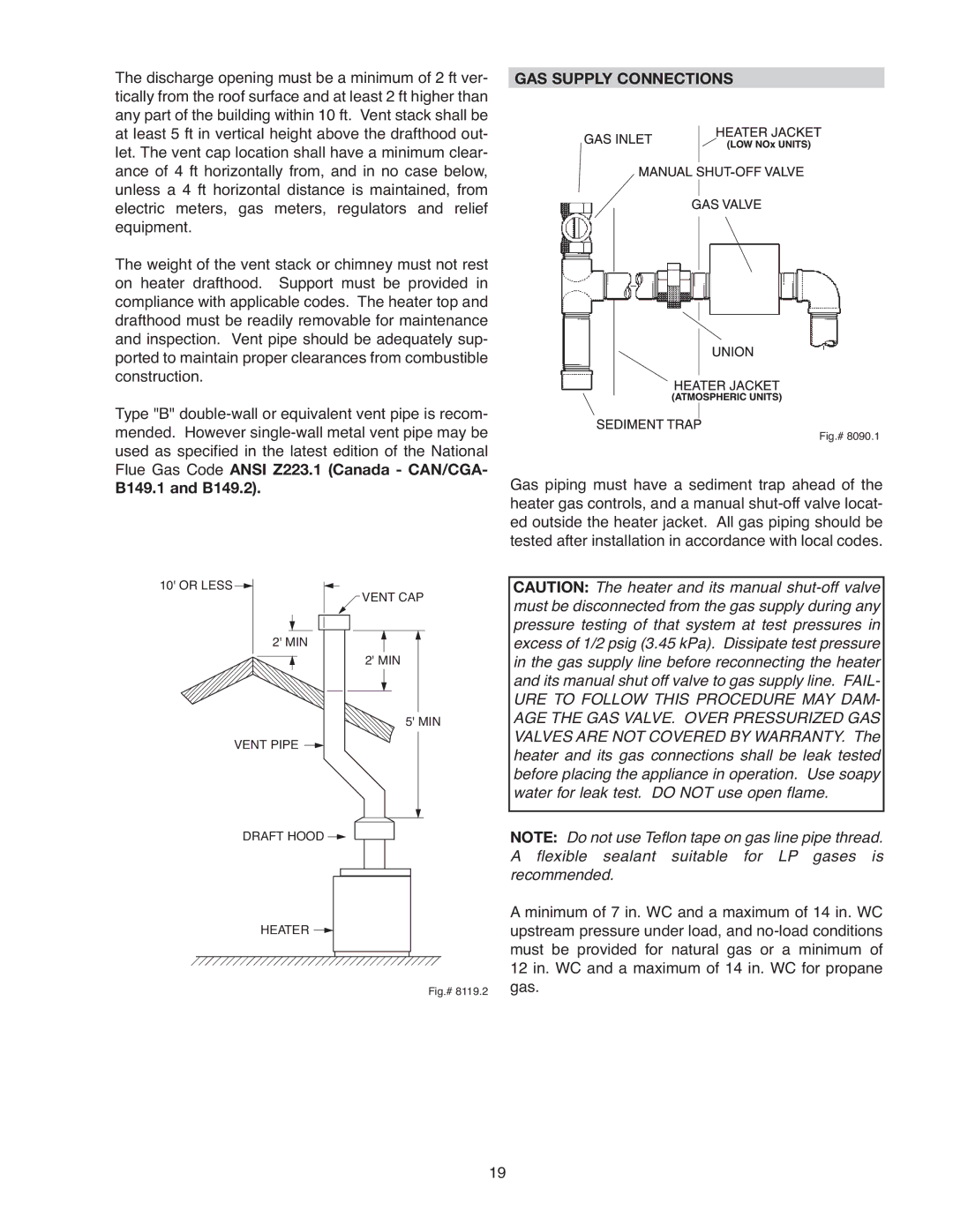
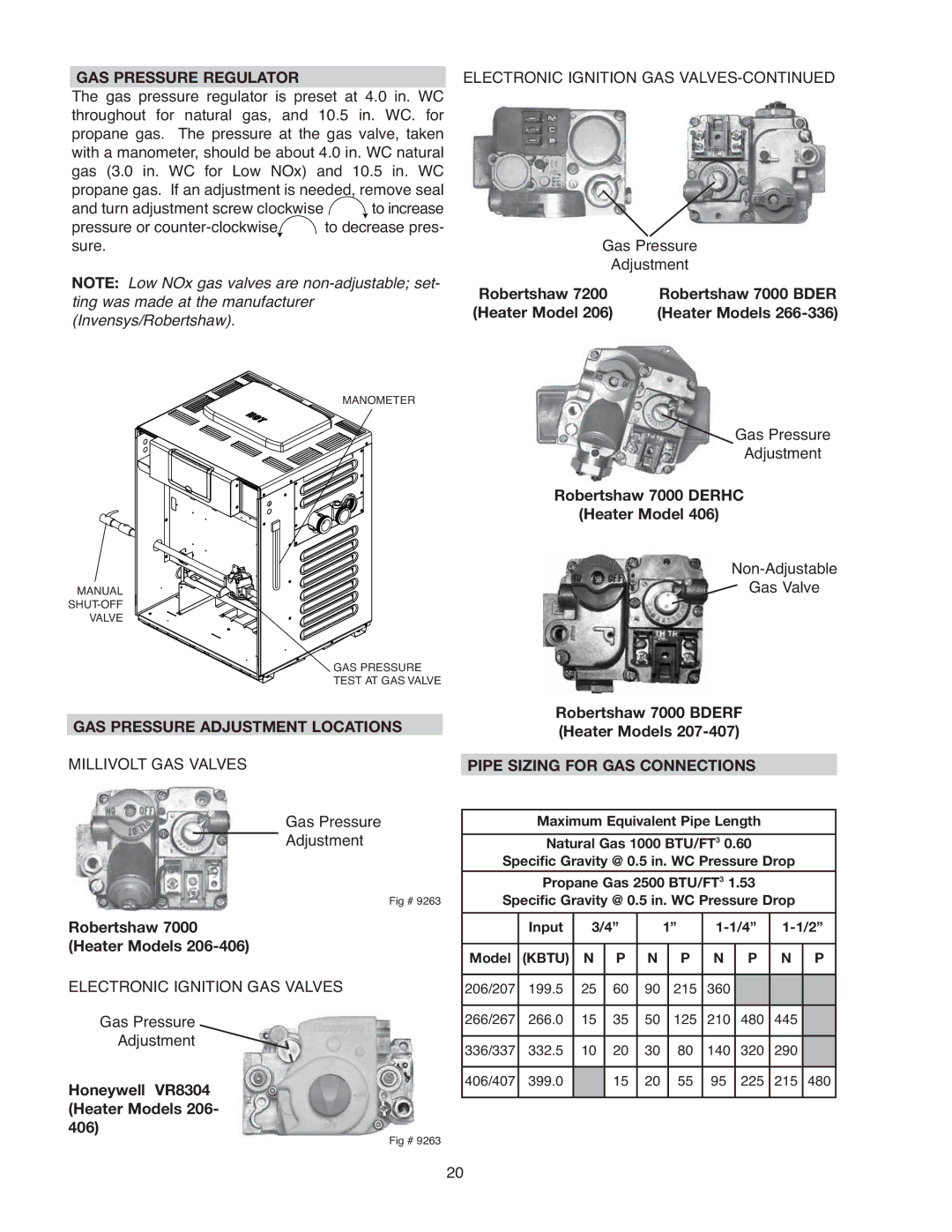
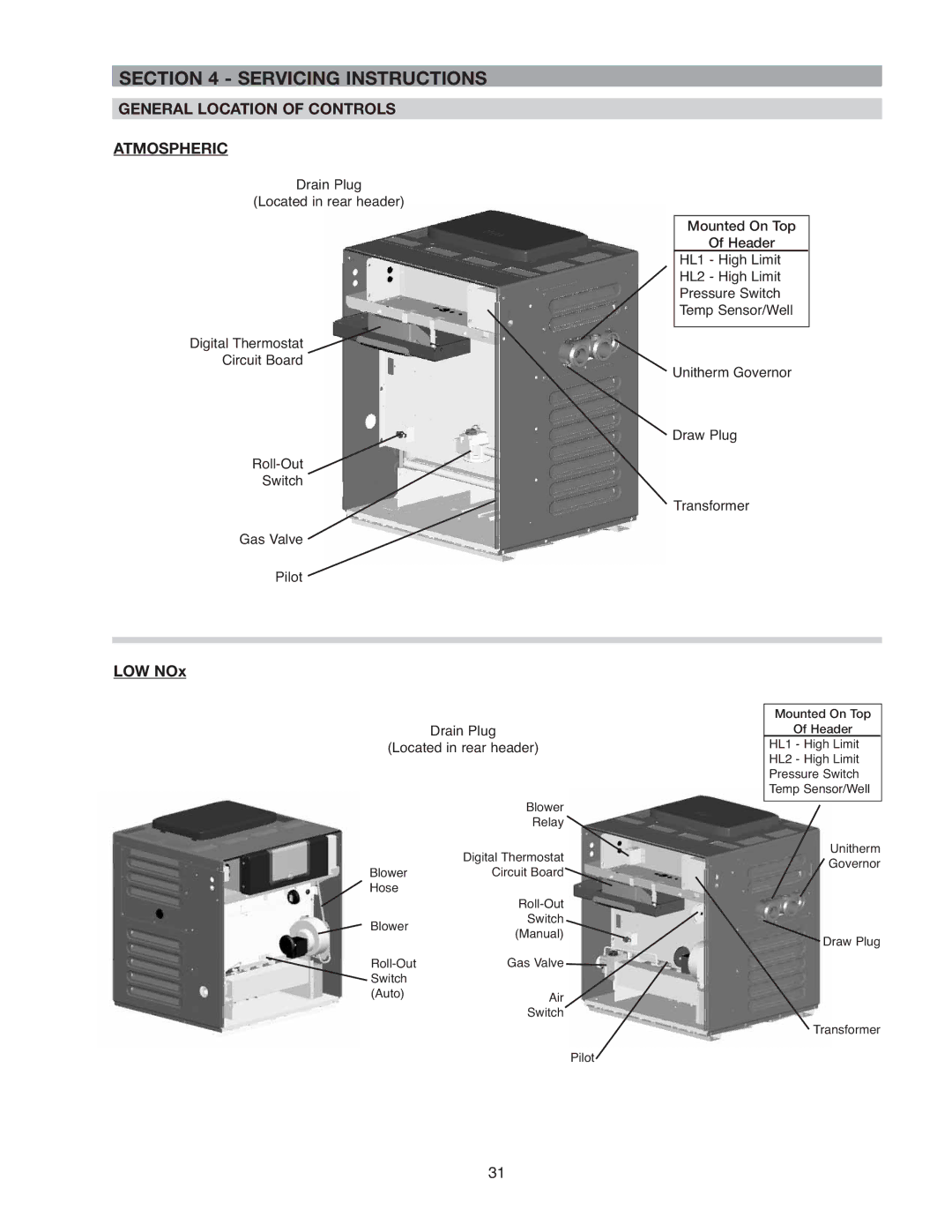
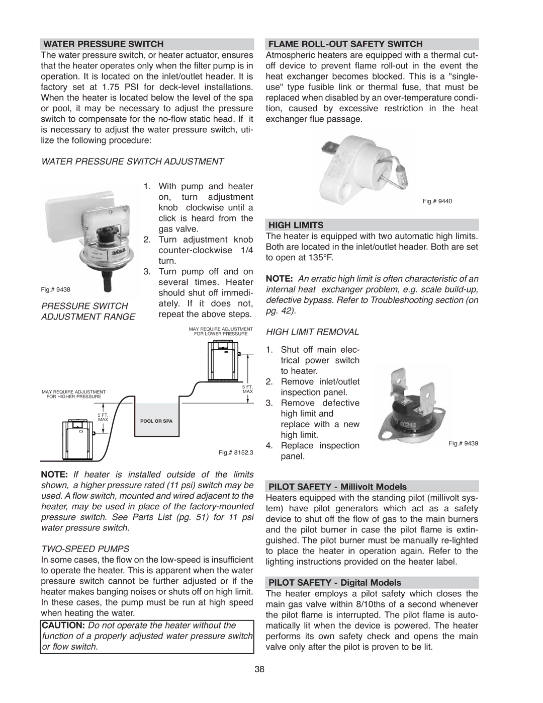
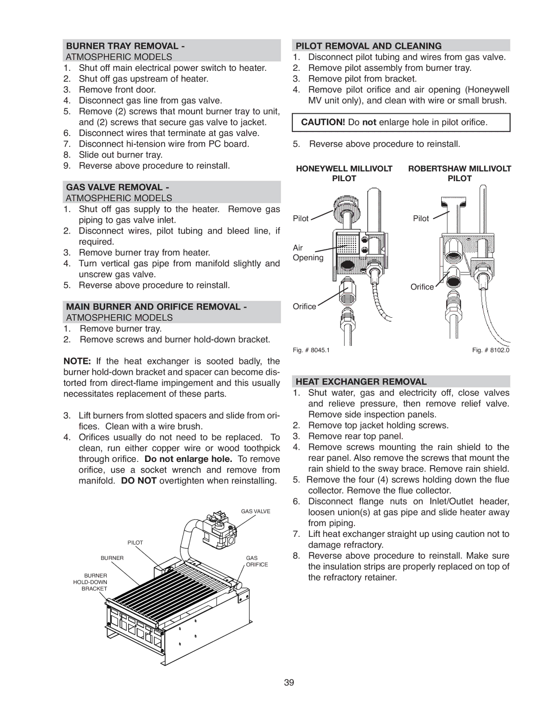
For 120 VAC input power to the unit, connect the black wire to the “L1” or hot leg of the power supply. Connect the white wire to the “Ret” or neutral leg of the power supply. Attach the wire nut to the red wire. There should be no connection to the red wire for 120 VAC operation. For Low NOx pool heaters attach a wire nut to each red wire independently.
120V ATMOSPHERIC HEATER | 120V LOW NOx HEATER |
SUPPLY
SIDE
HOT
L1
BLACK
RETURN
or
NEUTRAL WHITE
GROUND ![]()
![]()
![]()
![]() GREEN
GREEN
BLACK
WHITE
HEATER
4 WIRES
GREEN
RED
SUPPLY
SIDE
| HOT | BLACK | |
L1 |
| ||
BLACK | BLACK | ||
| |||
RETURN |
| WHITE | |
|
| ||
or | WHITE | WHITE | |
NEUTRAL | |||
|
| HEATER | |
|
| 7 WIRES | |
| GREEN | GREEN |
RED
RED
Fig. #9471
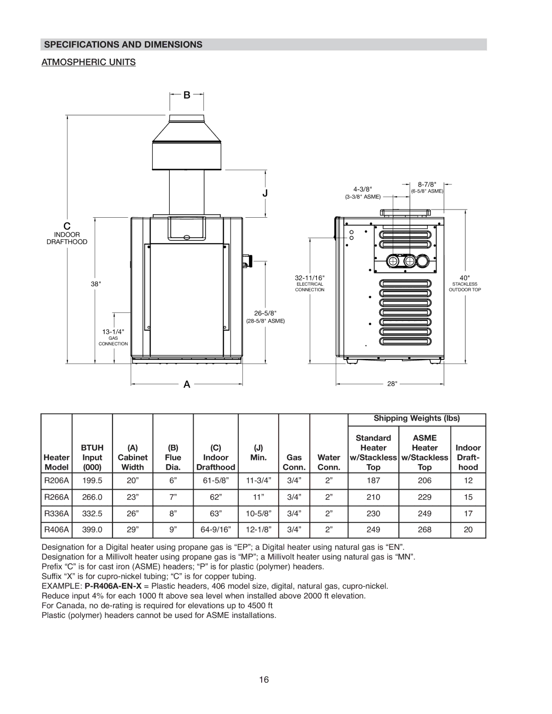
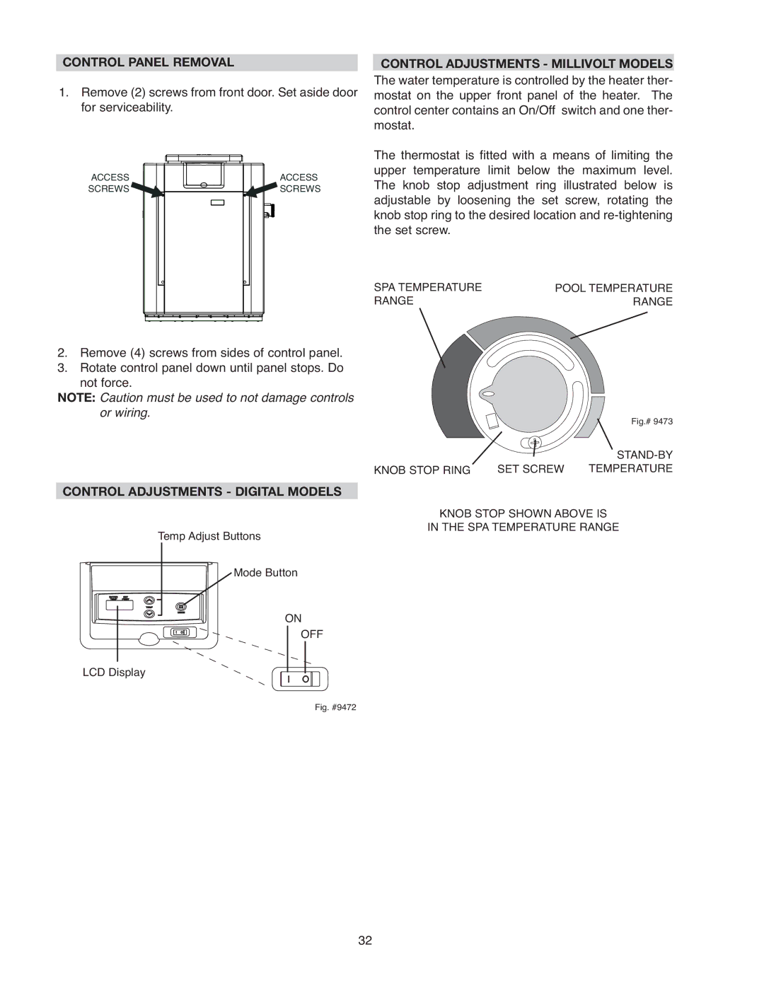
240 VAC WIRING
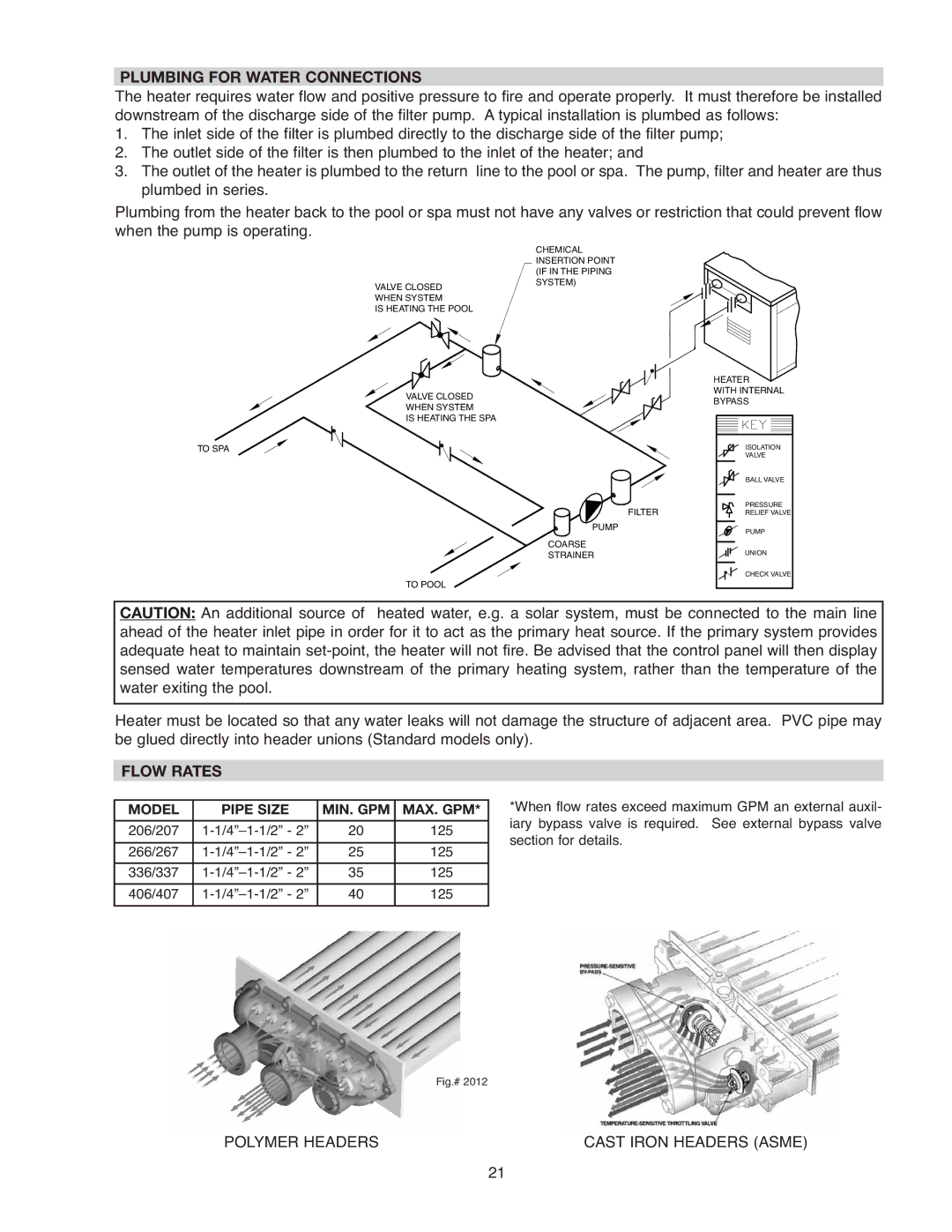
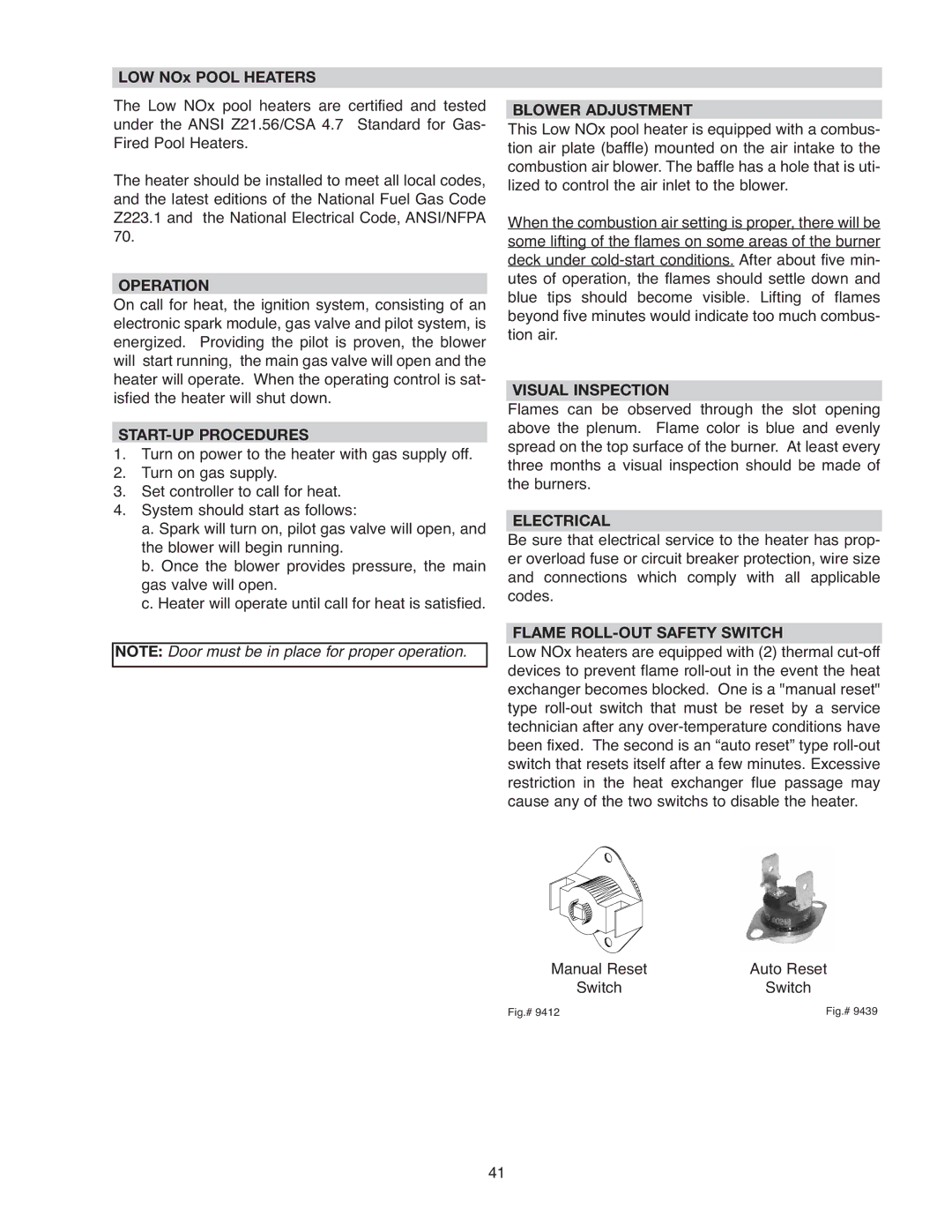
For 240 VAC input power to the unit, connect the black wire to the “L1” or hot leg of the power supply. Connect the red wire to the “L2” or second hot leg of the power supply. Attach the wire nut to the white wire. There should be no connection to the white wire for 240 VAC operation. For Low NOx pool heaters attach a wire nut to each white wire independently.
240V ATMOSPHERIC HEATER | 240V LOW NOx HEATER |
SUPPLY
SIDE
HOT
L1
BLACK
HOT
L2
RED
GREEN
BLACK
RED
HEATER
4 WIRES
GREEN
WHITE
SUPPLY
SIDE
HOT
L1
BLACK
HOT
L2
RED
GROUND ![]()
![]() GREEN
GREEN
BLACK
BLACK
RED
RED
HEATER
7 WIRES
GREEN
WHITE
WHITE
Fig. # 9471.1
Heater must be electrically grounded and bonded in accordance with local codes, or, in the absence of local codes, with the latest edition of the National Electrical Code, ANSI/NFPA 70. (Canada - Canadian Electrical Code, CSA C22.1, Part 1 and Part 2.)
NOTE: If the transformer’s primary side is wired for 120 VAC and 240 VAC is applied, damage to the transformer and PC board may result. Such damages are not covered under manufacturer’s limited warranty.
NOTE: Input power to the heater (120 or 240 VAC) can be supplied from the load (pump) side of time clock or directly from the GFCI power source. It is preferred to make connection to the load/pump side of the time clock. If using the switched GFCI power source, the heater could display false service indicators on the display panel if the pump is turned off.
27