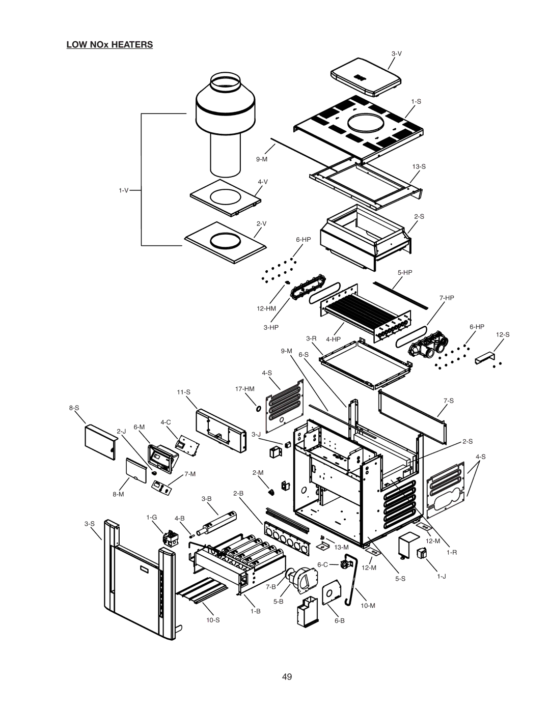
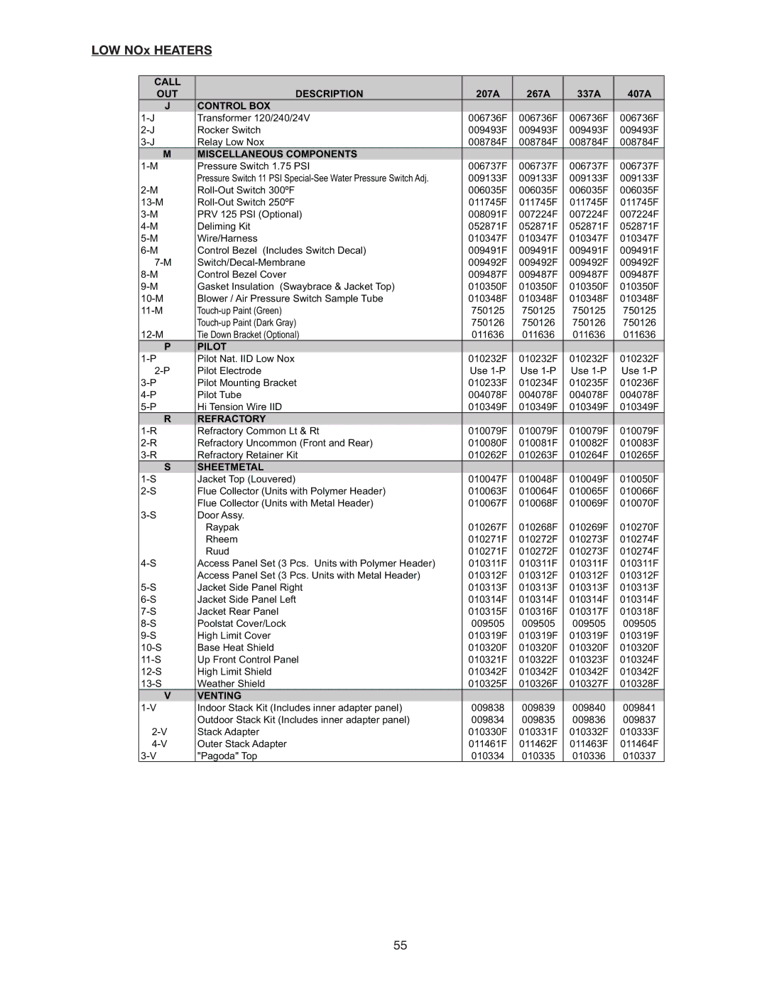
LOW NOx HEATERS
CALL |
|
|
|
|
|
OUT | DESCRIPTION | 207A | 267A | 337A | 407A |
J | CONTROL BOX |
|
|
|
|
Transformer 120/240/24V | 006736F | 006736F | 006736F | 006736F | |
Rocker Switch | 009493F | 009493F | 009493F | 009493F | |
Relay Low Nox | 008784F | 008784F | 008784F | 008784F | |
M | MISCELLANEOUS COMPONENTS |
|
|
|
|
Pressure Switch 1.75 PSI | 006737F | 006737F | 006737F | 006737F | |
| Pressure Switch 11 PSI | 009133F | 009133F | 009133F | 009133F |
006035F | 006035F | 006035F | 006035F | ||
011745F | 011745F | 011745F | 011745F | ||
PRV 125 PSI (Optional) | 008091F | 007224F | 007224F | 007224F | |
Deliming Kit | 052871F | 052871F | 052871F | 052871F | |
Wire/Harness | 010347F | 010347F | 010347F | 010347F | |
Control Bezel (Includes Switch Decal) | 009491F | 009491F | 009491F | 009491F | |
009492F | 009492F | 009492F | 009492F | ||
Control Bezel Cover | 009487F | 009487F | 009487F | 009487F | |
Gasket Insulation (Swaybrace & Jacket Top) | 010350F | 010350F | 010350F | 010350F | |
Blower / Air Pressure Switch Sample Tube | 010348F | 010348F | 010348F | 010348F | |
750125 | 750125 | 750125 | 750125 | ||
| 750126 | 750126 | 750126 | 750126 | |
Tie Down Bracket (Optional) | 011636 | 011636 | 011636 | 011636 | |
P | PILOT |
|
|
|
|
Pilot Nat. IID Low Nox | 010232F | 010232F | 010232F | 010232F | |
Pilot Electrode | Use | Use | Use | Use | |
Pilot Mounting Bracket | 010233F | 010234F | 010235F | 010236F | |
Pilot Tube | 004078F | 004078F | 004078F | 004078F | |
Hi Tension Wire IID | 010349F | 010349F | 010349F | 010349F | |
R | REFRACTORY |
|
|
|
|
Refractory Common Lt & Rt | 010079F | 010079F | 010079F | 010079F | |
Refractory Uncommon (Front and Rear) | 010080F | 010081F | 010082F | 010083F | |
Refractory Retainer Kit | 010262F | 010263F | 010264F | 010265F | |
S | SHEETMETAL |
|
|
|
|
Jacket Top (Louvered) | 010047F | 010048F | 010049F | 010050F | |
Flue Collector (Units with Polymer Header) | 010063F | 010064F | 010065F | 010066F | |
| Flue Collector (Units with Metal Header) | 010067F | 010068F | 010069F | 010070F |
Door Assy. |
|
|
|
| |
| Raypak | 010267F | 010268F | 010269F | 010270F |
| Rheem | 010271F | 010272F | 010273F | 010274F |
| Ruud | 010271F | 010272F | 010273F | 010274F |
Access Panel Set (3 Pcs. Units with Polymer Header) | 010311F | 010311F | 010311F | 010311F | |
| Access Panel Set (3 Pcs. Units with Metal Header) | 010312F | 010312F | 010312F | 010312F |
Jacket Side Panel Right | 010313F | 010313F | 010313F | 010313F | |
Jacket Side Panel Left | 010314F | 010314F | 010314F | 010314F | |
Jacket Rear Panel | 010315F | 010316F | 010317F | 010318F | |
Poolstat Cover/Lock | 009505 | 009505 | 009505 | 009505 | |
High Limit Cover | 010319F | 010319F | 010319F | 010319F | |
Base Heat Shield | 010320F | 010320F | 010320F | 010320F | |
Up Front Control Panel | 010321F | 010322F | 010323F | 010324F | |
High Limit Shield | 010342F | 010342F | 010342F | 010342F | |
Weather Shield | 010325F | 010326F | 010327F | 010328F | |
V | VENTING |
|
|
|
|
Indoor Stack Kit (Includes inner adapter panel) | 009838 | 009839 | 009840 | 009841 | |
| Outdoor Stack Kit (Includes inner adapter panel) | 009834 | 009835 | 009836 | 009837 |
Stack Adapter | 010330F | 010331F | 010332F | 010333F | |
Outer Stack Adapter | 011461F | 011462F | 011463F | 011464F | |
"Pagoda" Top | 010334 | 010335 | 010336 | 010337 |
55