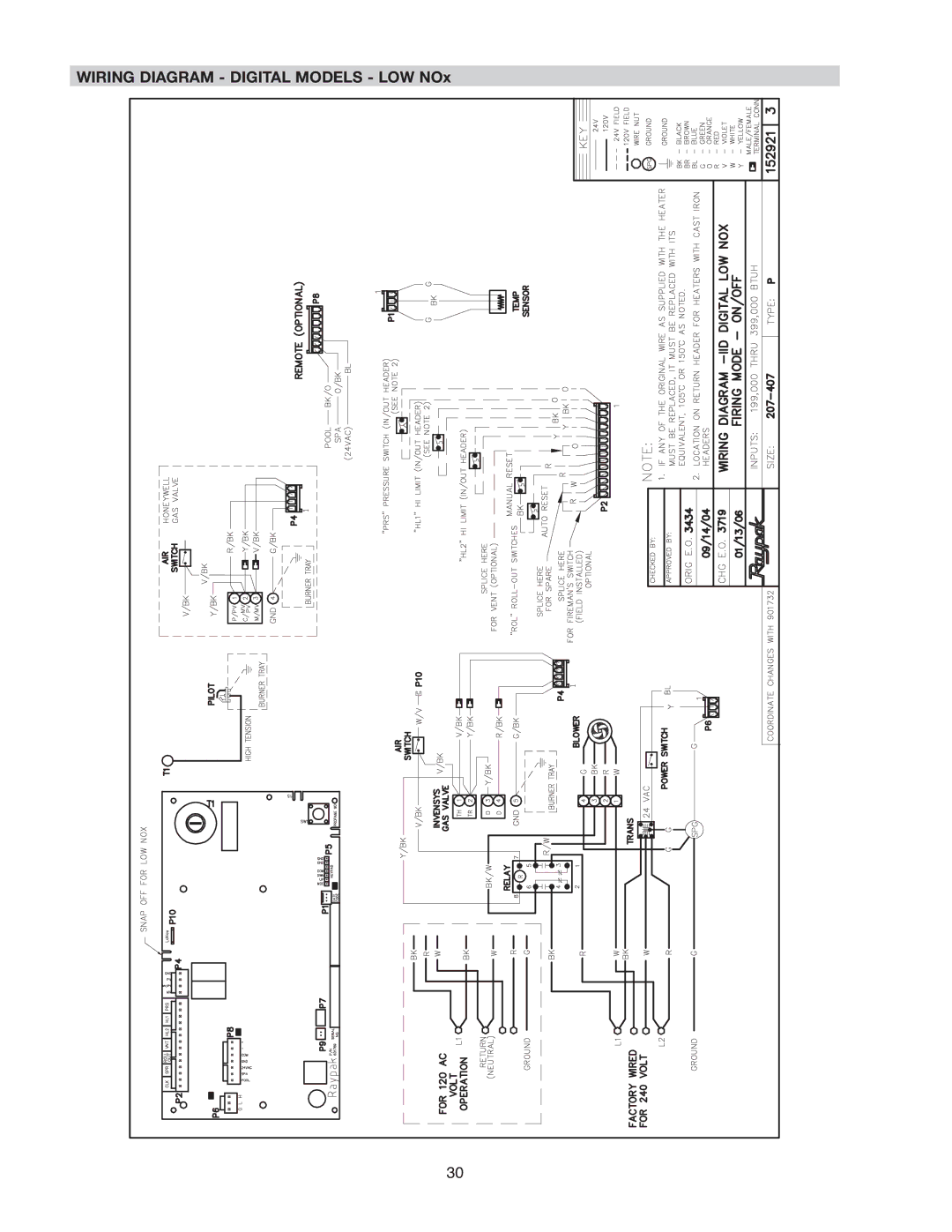
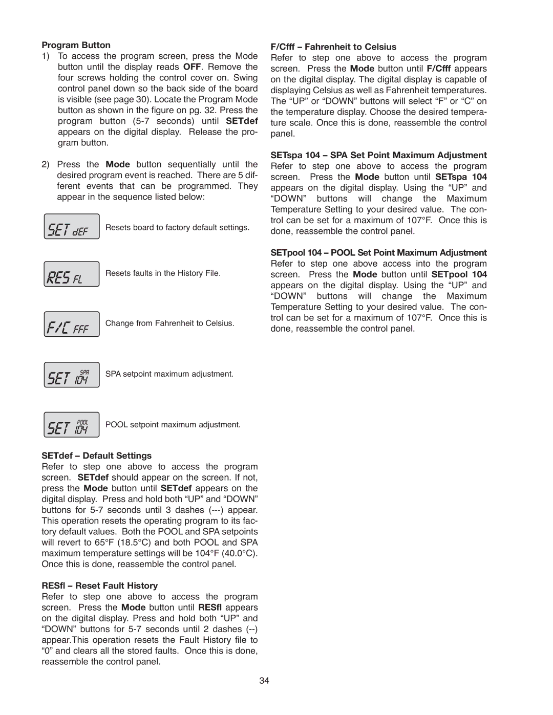

ELECTRICAL WIRING
NOTE: If it is necessary to replace any of the original wiring, use 105°C wire or its equivalent, and/or 150°C wire or its equivalent, like the original wiring.
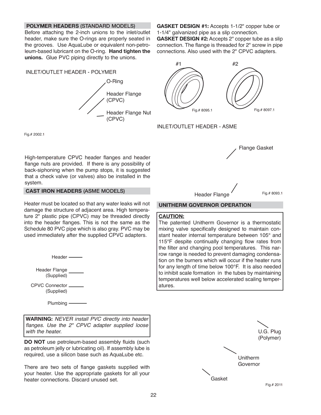
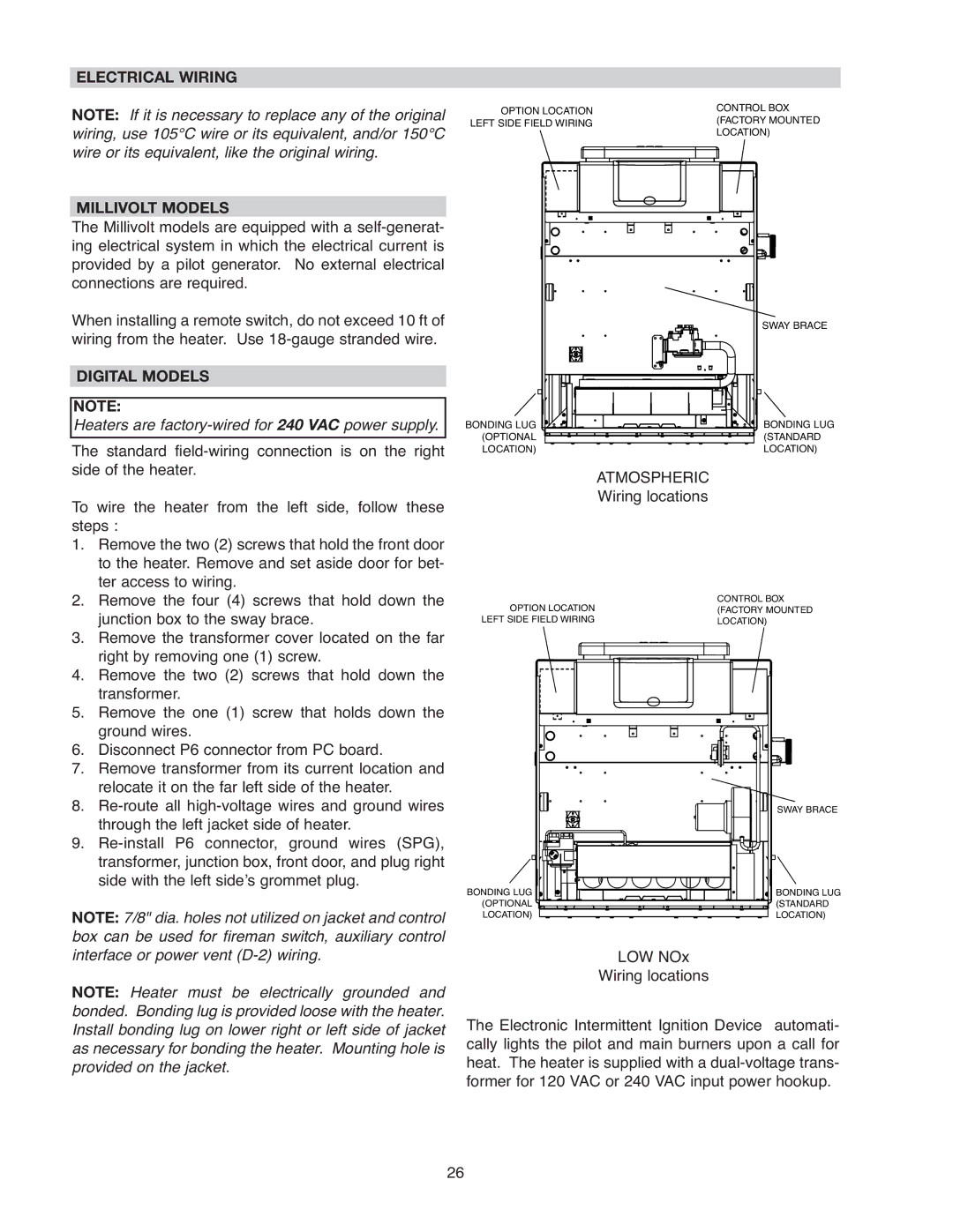
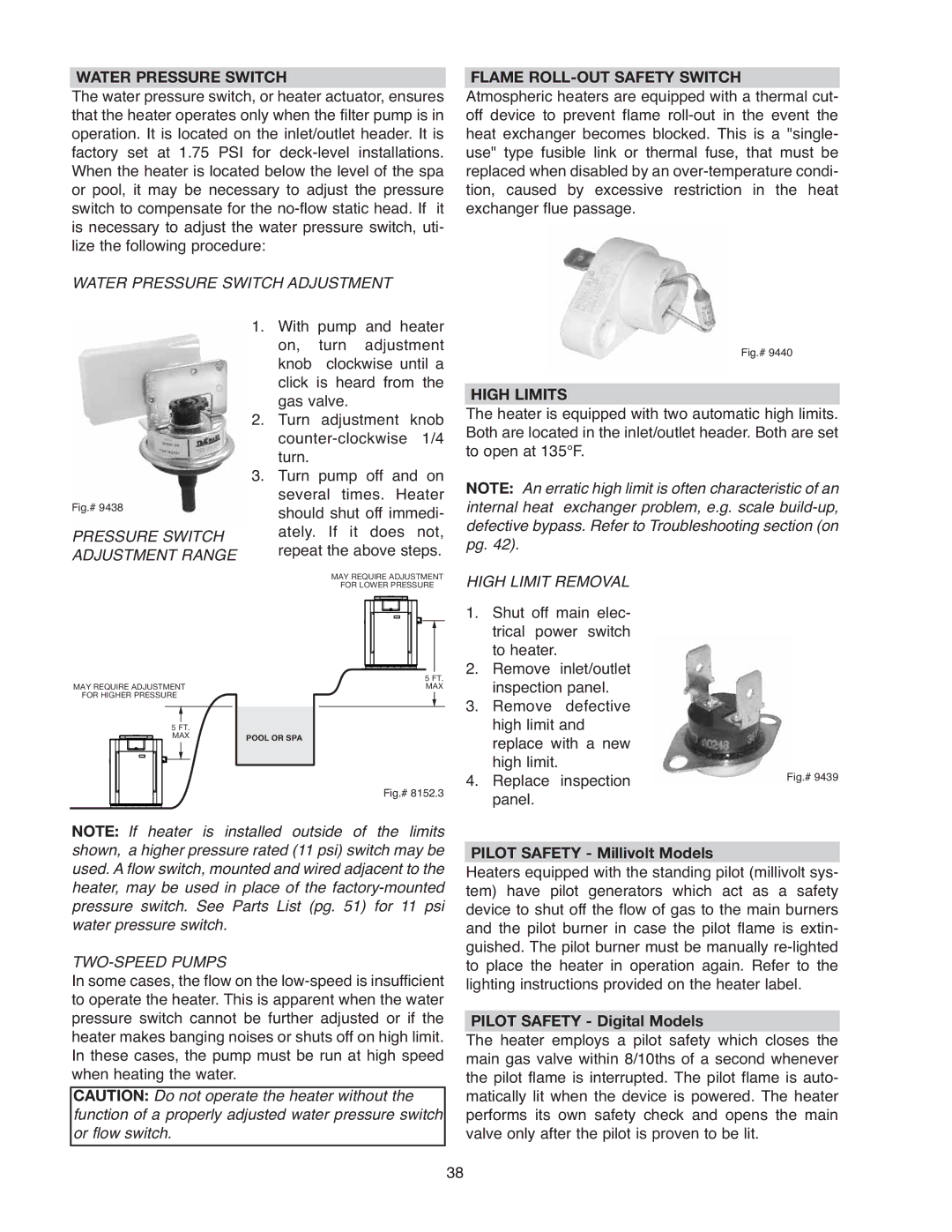
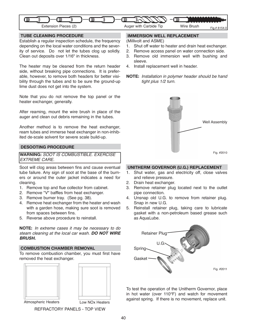
OPTION LOCATION | CONTROL BOX | |
(FACTORY MOUNTED | ||
LEFT SIDE FIELD WIRING | ||
LOCATION) | ||
|
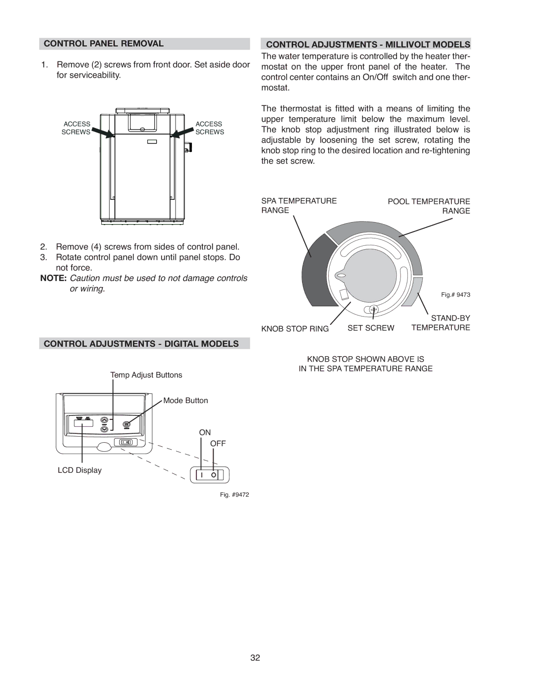
MILLIVOLT MODELS
The Millivolt models are equipped with a
When installing a remote switch, do not exceed 10 ft of wiring from the heater. Use
DIGITAL MODELS
NOTE:
Heaters are factory-wired for 240 VAC power supply.
The standard
To wire the heater from the left side, follow these steps :
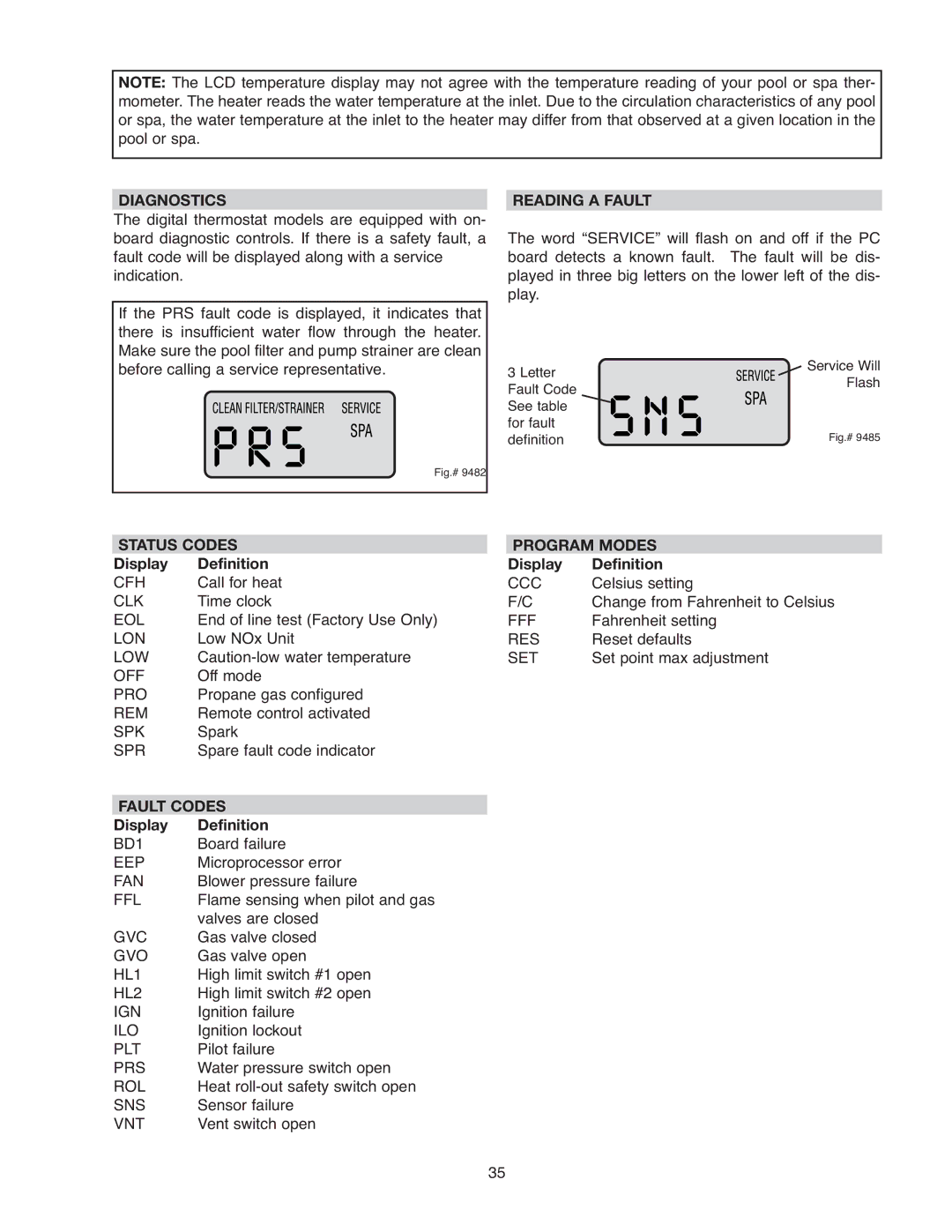
BONDING LUG (OPTIONAL LOCATION)
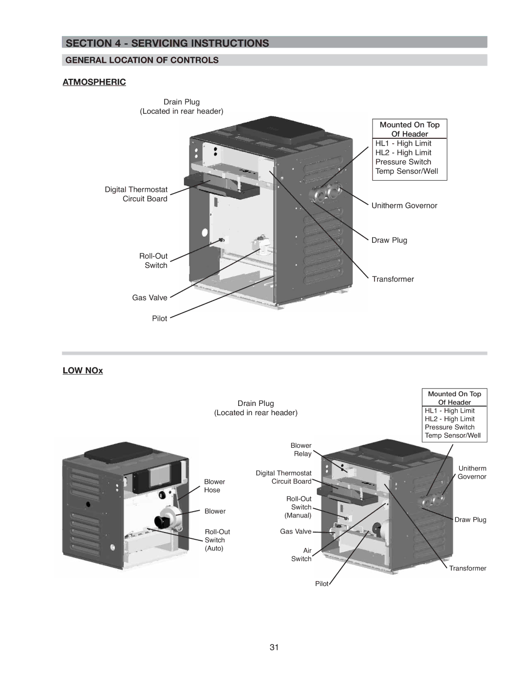
ATMOSPHERIC |
Wiring locations |
SWAY BRACE
BONDING LUG (STANDARD LOCATION)
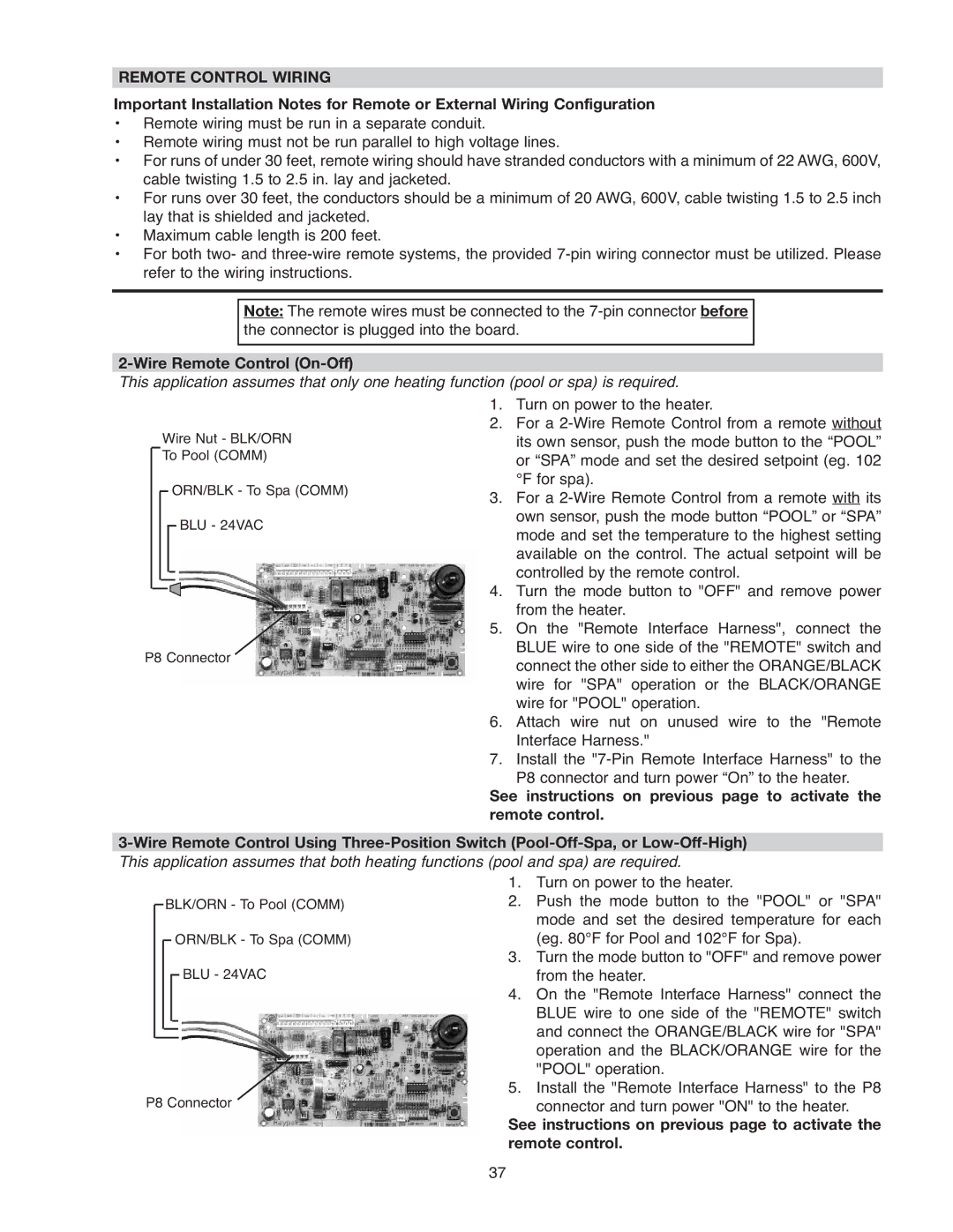
1. | Remove the two (2) screws that hold the front door |
| to the heater. Remove and set aside door for bet- |
| ter access to wiring. |
2. | Remove the four (4) screws that hold down the |
| junction box to the sway brace. |
3. | Remove the transformer cover located on the far |
| right by removing one (1) screw. |
4. | Remove the two (2) screws that hold down the |
| transformer. |
5. | Remove the one (1) screw that holds down the |
| ground wires. |
6. | Disconnect P6 connector from PC board. |
7. | Remove transformer from its current location and |
| relocate it on the far left side of the heater. |
8. |
OPTION LOCATION |
|
|
| CONTROL BOX | ||||||||||||
|
|
| (FACTORY MOUNTED | |||||||||||||
LEFT SIDE FIELD WIRING |
|
|
| LOCATION) | ||||||||||||
|
|
|
|
|
|
|
|
|
|
|
|
|
|
|
|
|
|
|
|
|
|
|
|
|
|
|
|
|
|
|
|
|
|
|
|
|
|
|
|
|
|
|
|
|
|
|
|
|
|
|
|
|
|
|
|
|
|
|
|
|
|
|
|
|
|
|
|
|
|
|
|
|
|
|
|
|
|
|
|
|
|
|
|
|
|
|
|
|
|
|
|
|
|
|
|
|
|
|
|
|
|
|
|
|
|
|
|
|
|
|
|
|
|
|
|
|
|
|
|
|
|
|
|
|
|
|
|
|
|
|
|
|
|
|
|
|
|
|
|
|
|
|
|
|
|
|
|
|
|
|
|
|
through the left jacket side of heater. |
9. |
transformer, junction box, front door, and plug right |
side with the left side’s grommet plug. |
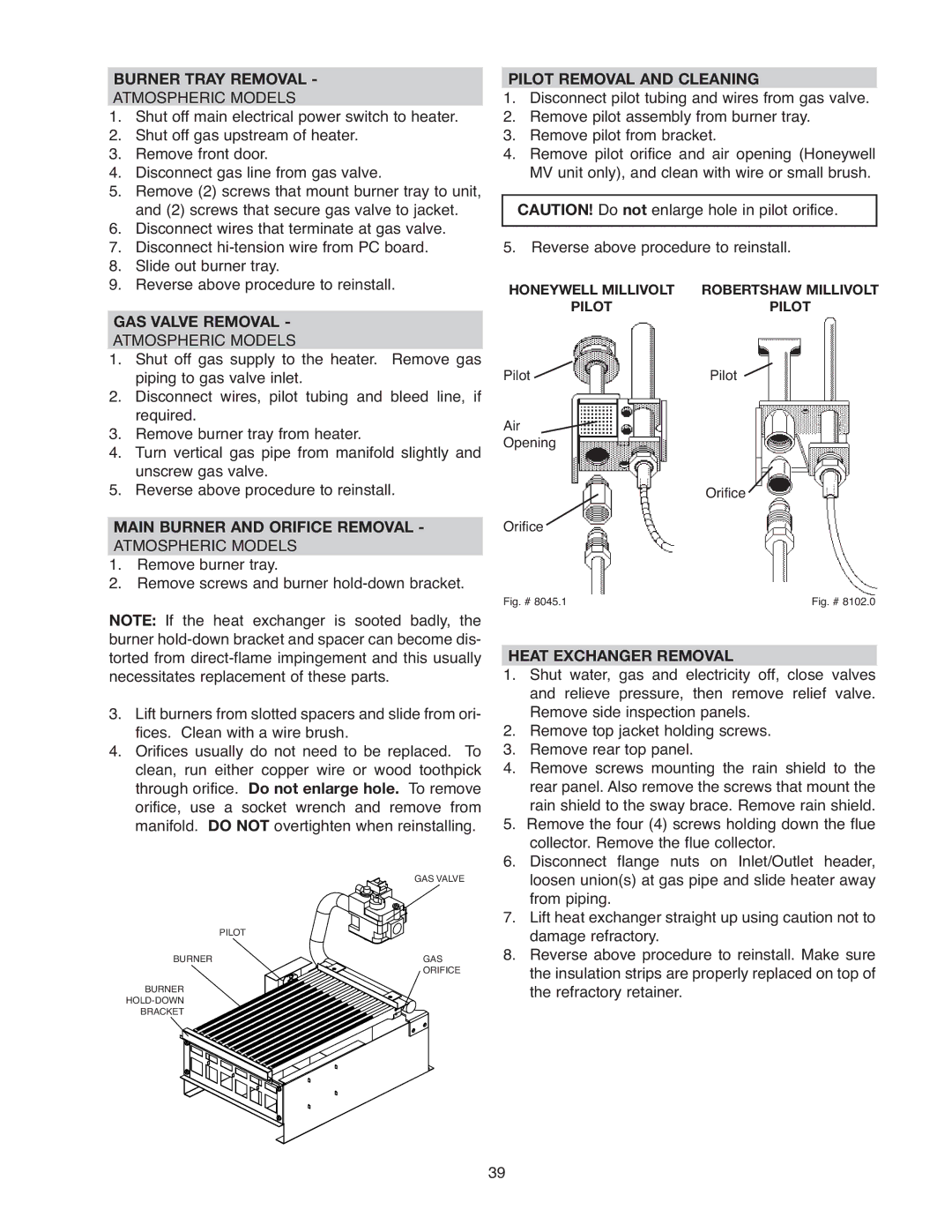
NOTE: 7/8" dia. holes not utilized on jacket and control box can be used for fireman switch, auxiliary control interface or power vent
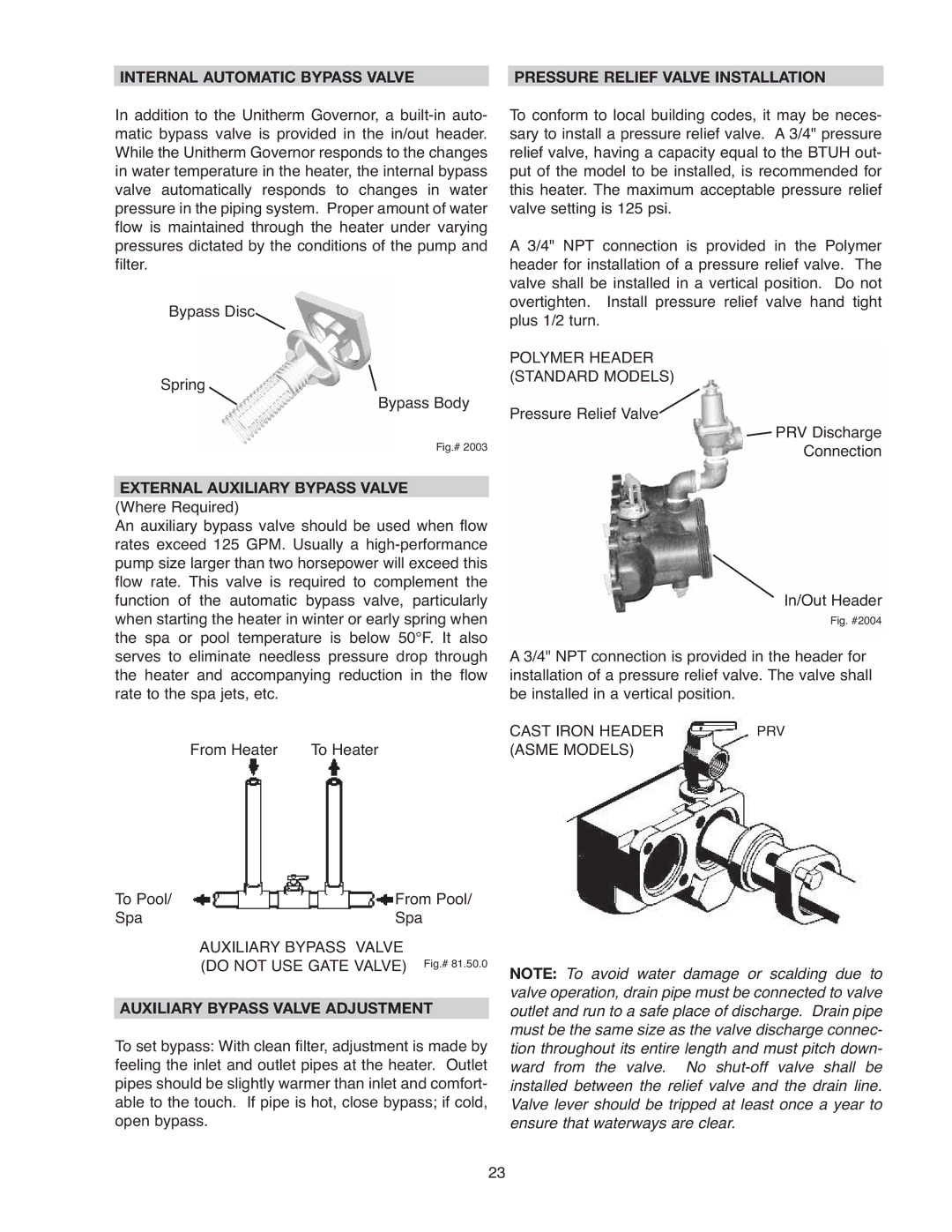
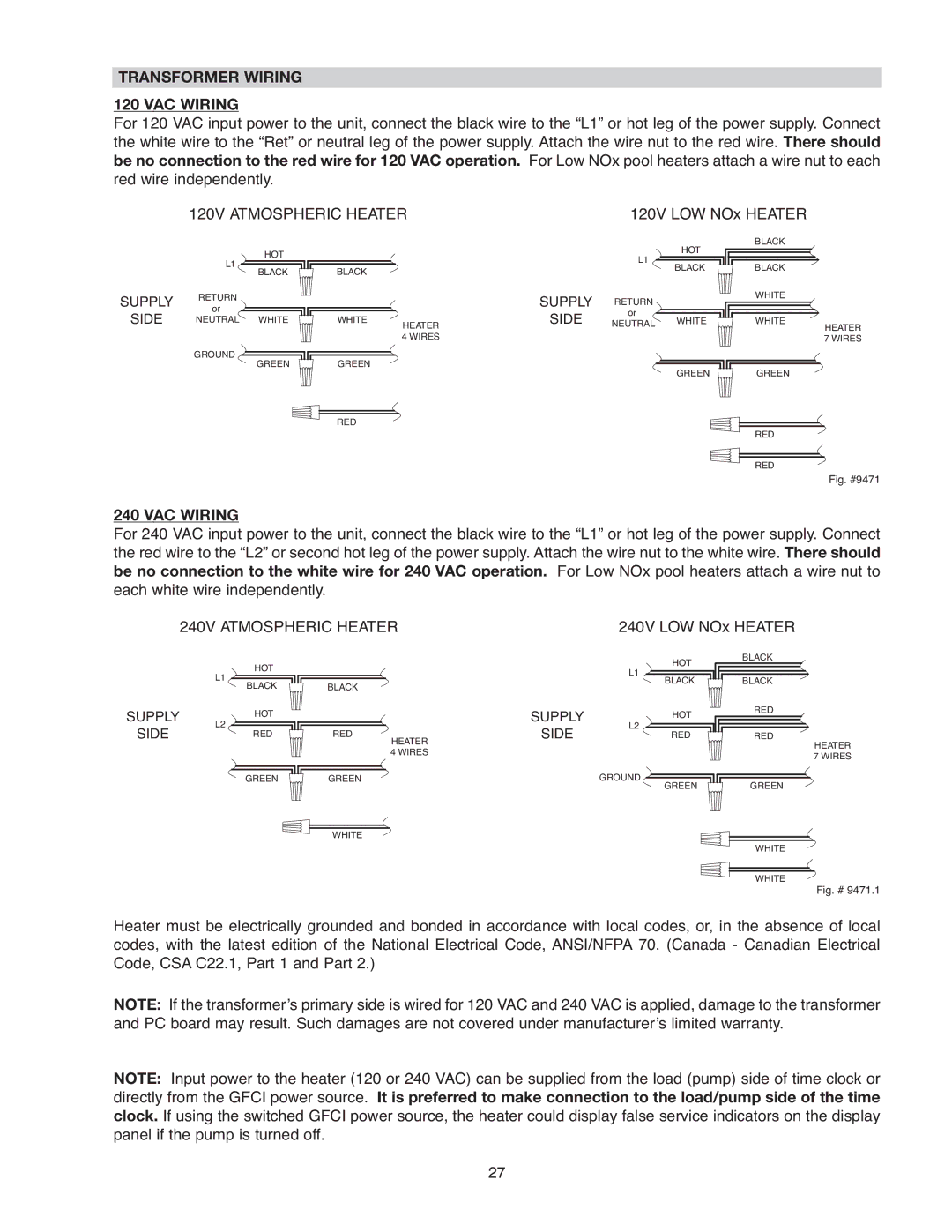
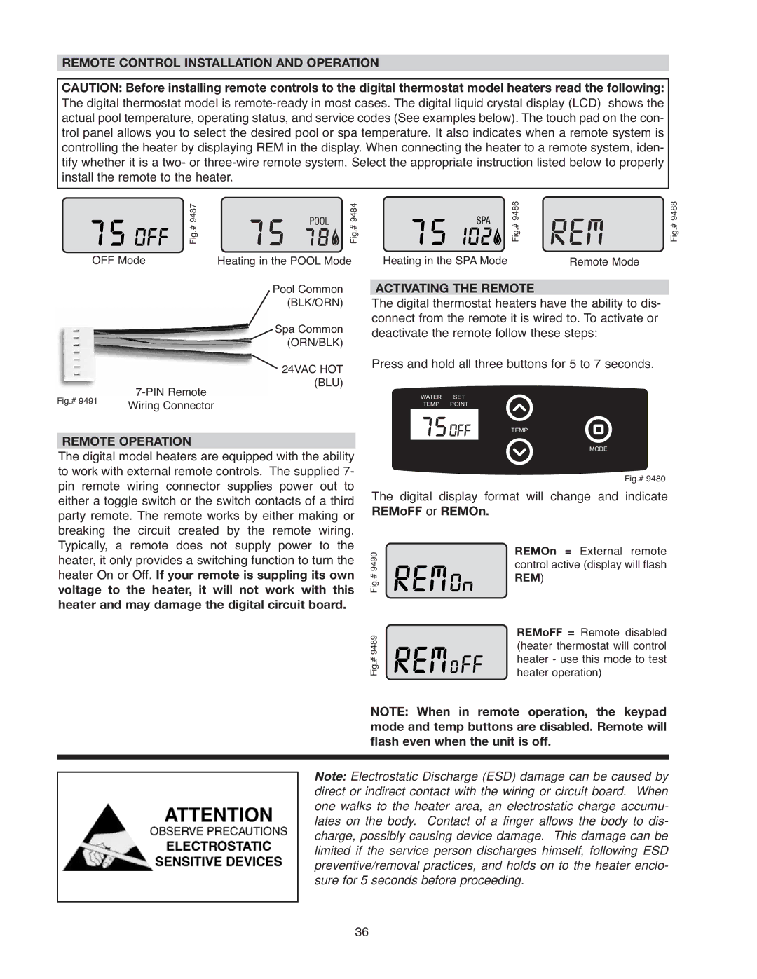
BONDING LUG (OPTIONAL LOCATION)
SWAY BRACE
BONDING LUG (STANDARD LOCATION)
LOW NOx
Wiring locations
NOTE: Heater must be electrically grounded and bonded. Bonding lug is provided loose with the heater. Install bonding lug on lower right or left side of jacket as necessary for bonding the heater. Mounting hole is provided on the jacket.
The Electronic Intermittent Ignition Device automati- cally lights the pilot and main burners upon a call for heat. The heater is supplied with a
26